17. Cable
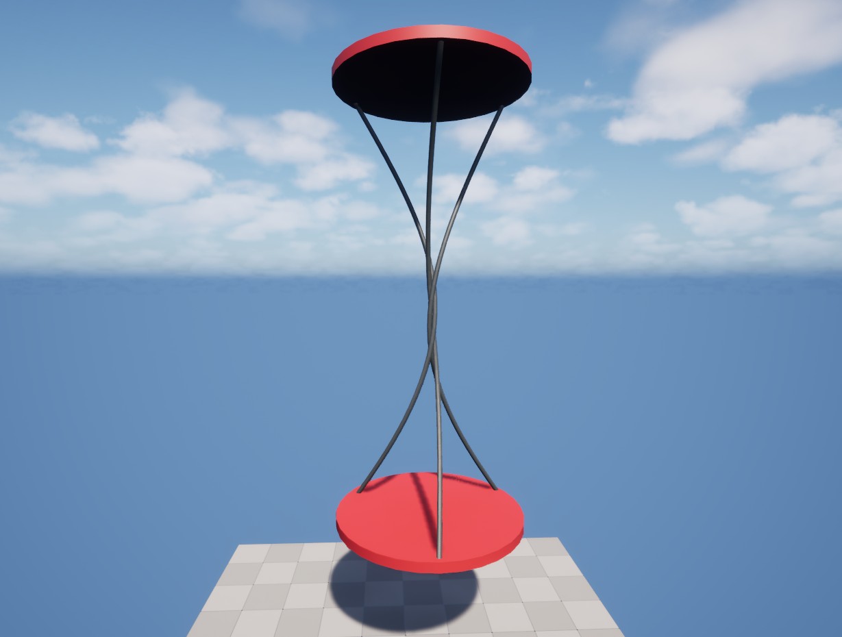
Multiple cables in a simple rotating mechanism.
AGX Cable is used to simulate cables, hoses, ropes, short wires and dress packs. It is a lumped element structure with a circular cross section that can be bent, stretched and twisted.
In contrast to Wire, Cable uses a fixed resolution, i.e. constant segment length and offers realistic contact interactions with other objects. The Wire can adjust the resolution dynamically in order to improve stability, making it possible to use them in scenarios with extreme tension and in large scale scenarios with several kilometers of wire. On the other hand, the Cable supports modeling of plasticity and torsion, which are not available for Wires.
It is possible to attach parts of a Cable to Rigid Bodies within the Simulation. This is explained in further detail in section Creating a Cable.
17.1. Creating a Cable
A Cable is created by adding a Cable Component to an Actor or a Blueprint.

Adding a Cable Component to a Blueprint.
Some overall properties such as the Radius and Segment Length can be set from the Cable Component’s Details panel.
Here, also Cable Rendering and Collision Groups can be configured.
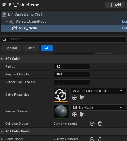
The Details Panel of a Cable Component.
The next step is typically to route the Cable, which is detailed in section Cable Route Nodes. To define the physical behavior of the Cable, a Cable Properties Asset should be assigned, see Cable Properties for details.
17.1.1. Cable Route Nodes
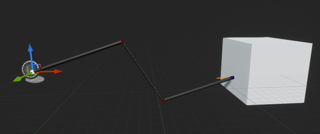
A routed Cable Component.
The initial Cable route is determined from a list of Route Nodes that can be accessed from the Cable Component’s Details Panel (but is mainly edited in the viewport).
In the image above, starting from the left, the first three Route Nodes are Free and the last one is Body Fixed and is attached to the Rigid Body owning the white Box.
Route Nodes are typically edited in the Viewport. Creating Route Nodes for a Cable is very similar to how Route Nodes are created for a Wire. To move a Route Node, select the Cable Component and then select the Route Node in the Viewport. Now, a transform widget will be shown and the Route Node can be moved.
To create a new Route Node, select an existing Route Node, hold down the alt key while dragging the Route Node with the transform widget.
Now a new Route Node will be placed at the end of the drag.
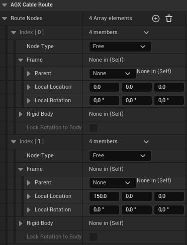
Route Nodes in a Cable Component’s Details Panel.
These nodes define the initial route of the cable at BeginPlay. After initialization, the route node list is no longer used or updated, and instead AGX Dynamics takes over and simulates the dynamic behavior of the Cable.
Route Nodes can be one of two types, either Free or Body Fixed.
Free Route Nodes are as the name suggests, free in the world (apart from being part of the Cable itself).
Body Fixed Route Nodes are used to attach the Cable to Rigid Bodies.
For Body Fixed Route Nodes the attachment can be done in one of two ways; either with locked rotation or unlocked rotation.
This is controlled with the Lock Rotation to Body property that can be found in the Details Panel for the Body Fixed Node.

Locking rotation of a Body Fixed Node.
When the Lock Rotation to Body property is enabled, a line will be rendered in the viewport indicating the orientation of the cable segment once the Simulation has started.
This orientation can be changed by rotating the Body Fixed Node in the viewport or manually changing the Local Rotation property in the Details Panel.
When the Lock Rotation to Body property is disabled, the rotation of the Route Node has no effect.
Note that the Route Nodes given by the user is only used as an approximate route for the Cable, and since the distance between user defined Route Nodes may not be evenly divisible with the fixed length of the segments, some overlap may occur.
This is detailed further in the AGX Dynamics User Manual.
If a route node has a Frame Parent set, the nodes Local Location is interpreted relative to that parent; otherwise the Cable Component itself is treated as the parent.
17.2. Cable Properties
Cable Properties is an Asset type that can be assigned to a Cable Component. These properties define how the cable behaves physically.
To create a Cable Properties Asset, right-click on the Content Browser and select the appropriate Asset type according to the image below:
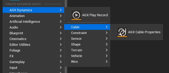
Creating a new Cable Properties Asset.
Here, properties such as Damping, Young’s Modulus and Poisson’s Ratio can be set for different directions or modes; bend, twist and stretch.
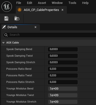
If no Cable Properties Asset is assigned to a Cable Component, the AGX Dynamics default values will be used during simulation.
17.3. Cable Rendering
By default, the Cable Component renders itself.
To change the render material, assign a material Asset to the Render Material property of the Cable Component from the Details Panel.
To change the apparent radius, without affecting the underlying physics simulation, the Render Radius Scale property can be set from the Cable Component’s Details panel.
This only affects the rendering of the Cable, and has no effect on the simulated Cable.
To disable the default rendering, disable the Visible property from the Cable Component’s Details panel.
For more advanced usage, such as custom rendering, the function GetNodeInfo can be used to access Cable node data, both during Play and when no simulation is running.