19. Track
AGX Track is used to simulate tracked vehicles. Each vehicle contains one or more tracks, and each track contains an arbitrary number of treads wrapped around two or more wheels. On the AGX Dynamics side the track is represented by a lumped element structure optionally making use of AMOR, AGX Dynamics’ merged body implementation, for improved performance. Each element of the lumped element structure is simulated by AGX Dynamics as a separate rigid body and is called a Track Node. The rigid bodies of consecutive Track nodes are linked together using hinge constraints. The bodies and hinges created by a Track are invisible from the Unreal Engine side, but we can still control some aspects of their configuration through the various properties and property assets provided by Track. See the agxVehicle: Tracked vehicles chapter of the AGX Dynamics user manual for more information about track, track wheel, and their properties. On the Unreal Engine side the Track is provided as an Actor Component that references Rigid Body Components to be used as wheels, along with parameters for each wheel and parameters for the track as a whole.
The Wheels created for a Track define the initial routing of the Track such that the track will follow the convex hull of the Wheels. The Track holds configuration parameters for each Wheel, but the Wheel itself is a Rigid Body Component separate from the Track and the position and geometry of the Wheels is defined by that Rigid Body.
This chapter starts with a step-by-step tutorial for how to create a minimal working Track setup and then continues with detailed descriptions of each of the Track’s parts.
19.1. Creating a Track
A Track is created by adding an AGX Track Component to an Actor or an Actor Blueprint.
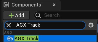
Add a Track Component to a Blueprint class.
The Track’s Details panel contains a number of settings, a few asset references, and a list of Track Wheels. The individual properties are described in Track Properties.
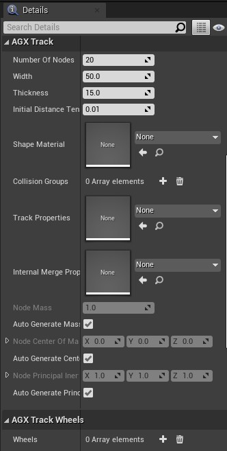
A Track Component’s Details panel. For more information see Track Properties.
19.1.1. Adding Wheels
Wheels are added to the Track in the AGX Track Wheels section of the Track’s Details panel. Each element of the Wheels array contains a reference to a Rigid Body Component and a set of properties for the Wheel. For more information on the Wheel properties, see Track Wheel.
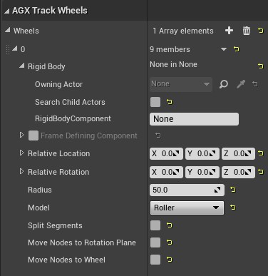
The Details panel section where a Track Wheel is configured.
All properties except for the Rigid Body have default values. To associate the Wheel with a Rigid Body type the name of the Rigid Body in the Rigid Body > RigidBodyComponent property, or select from the drop-down list if available. If the Track is in an Actor instance, i.e. not a Blueprint class, and the Rigid Body is in another Actor then Owning Actor can be set to that other Actor. By default, when Owning Actor is None, the Rigid Body will be searched for in the Actor that owns the Track. For instructions for how to create bodies and shapes, see Rigid Body.
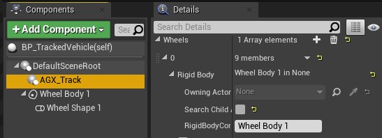
A Track Wheel’s Details panel with a Rigid Body reference assigned.
When there is at least one Wheel with a Rigid Body then selecting the Track in the Components panel will render the Track’s nodes, i.e. the individual lumped element elements, in the Viewport.
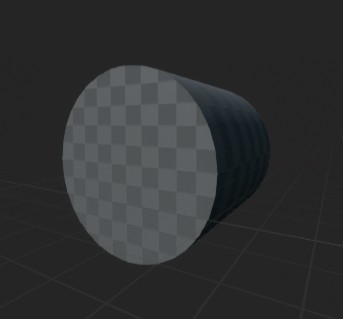
Rigid Body before being referenced from Wheel. |
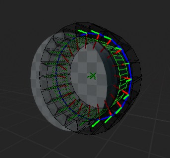
Rigid Body after being referenced from Wheel. |
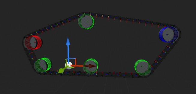
By adding more Rigid Bodies and more Wheels referencing those Rigid Bodies we get a longer route for the Track and the viewport visualization is updated to show the new route and the position of the nodes between and around the wheels.
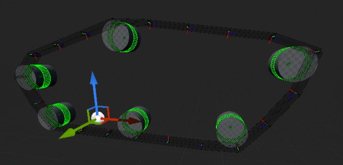
Visualization of a multi-Wheeled Track in the Blueprint editor viewport.
Since the Track is now longer each node has also been made longer compared to when there was only a single Wheel in order to fill the entirety of the Track without gaps. To reduce the size of each node we can increase resolution of the Track by increasing the Number Of Nodes property in the Track’s Details panel.
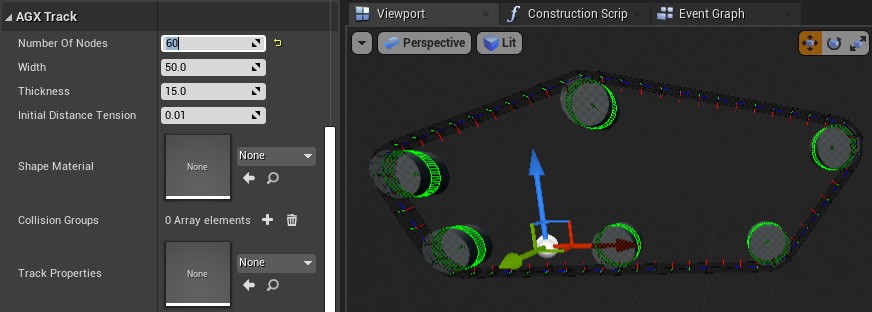
Increasing the Number Of Nodes property increases the resolution of the Track.
Each Wheel has a Model property which controls how it interacts with the Track. The three Model types are
Sprocket: Driving wheel - this wheel’s shaft is connected to the power-line/motor. Sprockets are normally geared so that the treads won’t slip while in contact with the surface of the sprocket. In AGX Dynamics this is implemented by merging the Track node’s rigid body to the sprocket’s rigid body.
Idler: Geared, non-powered wheel. Similar surface properties as the sprocket but this model isn’t powered. Will also merge with Track node rigid bodies.
Roller: Intermediate track-return or road wheel. Does not merge with Track node rigid bodies. Can split merged Track node segments.
Make the right-most wheel, the front of the vehicle, an Idler, the left-most wheel, the back of the vehicle, a Sprocket, and the rest Rollers. The wheel visualization will change color to indicate each wheel’s Model.
19.1.2. Building a Vehicle
To get a working vehicle we add a chassis, implemented as a Rigid Body with a Box Shape, and Hinges connecting each wheel Rigid Body to the chassis Rigid Body. Enable the Target Speed Controller on the left-most, i.e. rear, Hinge, the one who’s Wheel we assigned the Sprocket Model, and set the Target Speed to 100 degrees per second.
For more details on how to create Rigid Bodies and Constraints, see the Rigid Body and Constraints chapters of this user manual.
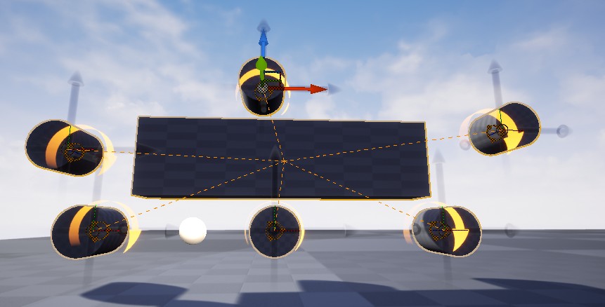
Vehicle with chassis body and a Hinge for each Wheel
19.1.3. Rendering
Though we can see the Track while it is selected thanks to the Track Visualizer, during runtime we need another form of rendering. The Track Component doesn’t dictate a rendering implementation, but it does provide information about the track treads that a renderer can use. An example renderer is included in the form of the Track Renderer Component. This is an Instanced Static Mesh based renderer that renders a Static Mesh at the location of each Track thread. To add rendering of our Track create a Track Renderer Component and attach it as a child to the Track Component. The Track Renderer needs a Static Mesh Asset to render at each Track node location. Assign the engine-included 100x100x100 Cube static mesh to the Static Mesh property of the Track Renderer. The renderer will scale the Static Mesh to fit within the size of the Track nodes, based on the size specified by Local Mesh Bounds Min and Max.
19.1.4. Final Result
Adding our Blueprint to a level and starting a Play In Editor session produces the following:
Video of the Track creation and Wheel configuration process:
19.2. Importing a Track
A Track can be imported from an existing AGX Dynamics archive (.agx). Some limitations apply in this case, which is detailed in Wire and Track Import Limitation.
19.3. Track Properties
Name |
Unit |
Description |
|---|---|---|
Track Implementation |
Selects the runtime track model. The default implementation uses a compact set of bodies and constraints, with the degrees of freedom determined by the number of wheels rather than the number of track nodes. FullDOF uses the older lumped-element model where each track node is simulated explicitly. |
|
Chassis |
Rigid Body used by the default track implementation as the chassis/reference body. |
|
Number Of Nodes |
The number of thread nodes to create. |
|
Width |
cm |
The width of the track. |
Thickness |
cm |
The thickness of the track. |
Initial Distance Tension |
cm |
Initial distance between node edges. |
By default, Track uses the AGX Dynamics default track model. It does not simulate individual track shoes explicitly, but instead uses a compact set of bodies and constraints where the degrees of freedom are determined by the number of wheels rather than the number of track nodes. Between each pair of wheels, a sensor box body is introduced and constrained to the chassis, while the track nodes are animated from wheel geometry and rotational motion for visual rendering. This gives a stable and efficient simulation, is better at handling high speeds, and often provides improved overall stability. It requires that the Chassis property is set. To use the older model where each Track node is simulated explicitly, set Track Implementation to FullDOF.
A Track has a fixed number of nodes, also called treads or segments, that is set with the Number of Nodes property. Routing a longer Track with unchanged Number Of Nodes will cause each node to be longer.
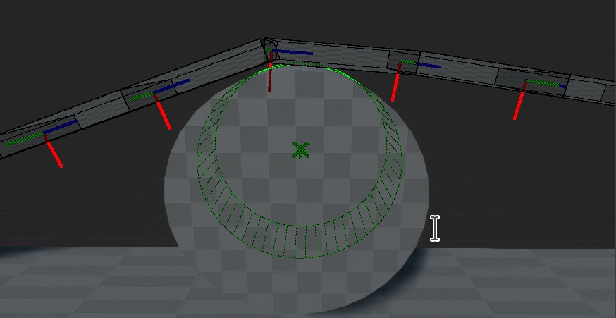
Track with Number Of Nodes set low. |
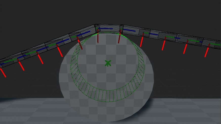
Track with Number Of Nodes set high. |
The width and thickness of the Track is set explicitly. The width always grows from the center of the wheels, and the thickness always grows from the surface of the wheel.
Initial Distance Tension is a gap, for distances > 0, or overlap, for distances < 0, measured in cm, between consecutive nodes in the Track during initialization. Setting the distance larger than zero will make the nodes shorter than what they would need to be to exactly reach around the track. At the start of the simulation the constraints holding the nodes together will apply a force between consecutive pairs of nodes to pull them together again. This will increase the tension in the Track. Setting the distance smaller than zero will make nodes longer instead, creating a Track that starts off compressed and will expand at the start of the simulation. This will reduce the tension in the Track. Finding a suitable Track tension is vital for both Track behavior and simulation stability.
19.3.1. Asset Properties
The Track Component contains a few properties that are references to assets that contain additional configuration parameters. Since they are assets it is possible to share these properties among multiple Track instances.
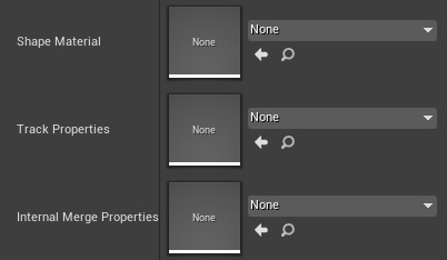
The Track properties that are stored in assets.
19.3.1.1. Shape and Contact Material
During initialization an AGX Dynamics Rigid Body and a Shape is created for each Track node. The Shape Material set on the Track’s Shape Material property is assigned to each such created Shape. For more details on Shape Material, and the associated Contact Material, see Materials.
High-quality friction between the track and the ground is of vital importance to simulations of tracked vehicles. It is therefore important to use a Contact Material that has been configured in a way suitable for the vehicle and ground in question. Contacts in general and direct friction in particular are costly in terms of computation time and a Track often produces a lot of contact points (see Contacts) between itself and the ground. Moreover, a track has very different friction behavior in the forward-backwards direction, also called the primary direction, compared to the left-right direction, also called the secondary direction. AGX Dynamics provides dedicated Track friction models for this, where the primary direction is computed from the interacting tracks instead of from a manually specified reference frame.
A good starting point is to use one of the Track friction models on the Contact Material used for contacts between the Track’s Shape Material and the ground’s Shape Material:
Track Box Friction
Track Scaled Box Friction
Track Iterative Projected Cone Friction
To account for the separation of parameters along the track versus orthogonal to the track enable the Secondary Friction Coefficient and Secondary Surface Viscosity checkboxes. Typically, friction should be lower and viscosity higher for the secondary direction compared to the primary direction. When using one of the Track friction models no reference frame properties need to be configured on the Contact Material.
Older setups based on Oriented friction models are still supported. When using an Oriented Friction Model the Oriented Friction Reference Frame Actor, Oriented Friction Reference Frame Component, and Primary Direction properties must still be configured explicitly.
You can read more about setting contact material parameters for Tracks, and tips for how to configure them, in the Simulation Parameters section of the agxVehicle: Tracked vehicles chapter in the AGX Dynamics user manual.
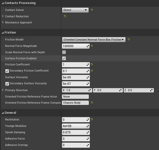
A Contact Material configured for use with a Track. Other Tracks may need different property values.
19.3.1.2. Track Properties
The Track Properties asset contains Track properties that can be shared among multiple Tracks.
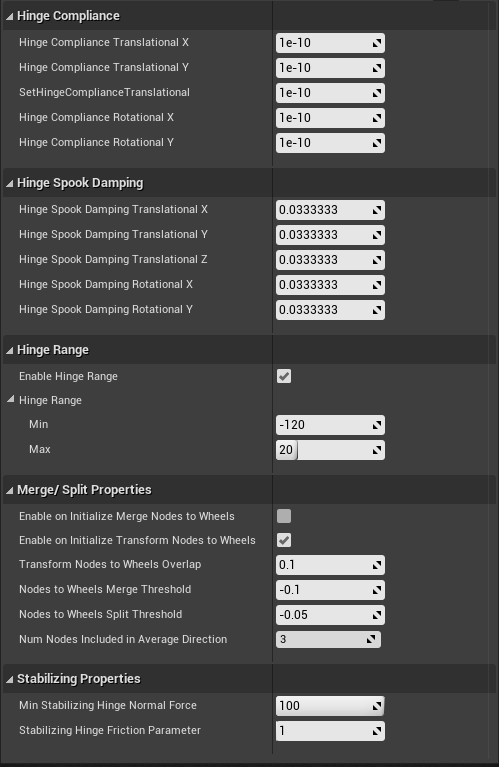
Properties available in the Track Properties asset.
The Track Properties asset contains stiffness and attenuation parameters for bending, shear, tensile, and torsional behavior, as well as the hinge range and merge/split behavior of the track.
The Merge / Split Properties deal with the way nodes are merged to Sprocket and Idler wheels when using the FullDOF track implementation.
You can read more about the Track Properties in the Track Properties section of the agxVehicle: Tracked vehicles chapter of the AGX Dynamics user manual.
19.3.1.3. Internal Merge Properties
A Track can be configured to use AMOR to merge the rigid bodies of groups of consecutive nodes together to a single AGX Dynamics Rigid Body. Such a group is called a segment. Merging multiple nodes to a segment improves both runtime performance and simulation stability. Track node merging is enabled in the Internal Merge Properties asset assigned to the Track by checking the Merge Enabled checkbox. For each Track there is a limit to the number of nodes that can be merged per segment. This limit is also set in the Internal Merge Properties asset.
Nodes will only be merged into a segment when they are aligned, i.e. they form a straight track segment. This is unlikely to happen by itself, so when merging is enabled the Lock Controller on each hinge linking Track node bodies together is also enabled and will add a torque between the nodes to align them. The compliance and damping of these locks can be set on the Internal Merge Split Properties asset. The compliance should be set low enough for the Track nodes to eventually align, but not so low that it has a detrimental effect on the stability and accuracy of the simulation. If you observe sudden and jittery movement around Sprocket and Idler wheels then the compliance may be set too small.
The hinge Lock Controllers can be disabled even with merging enabled by unchecking Lock To Reach Merge Condition Enabled in the Internal Merge Properties.
Track nodes are only merged when they are aligned. The maximum allowed merge angle, i.e. the angle threshold that must be reached for two nodes to be considered aligned and thus merged, can be configured in the Internal Merge Properties. The angle merge condition is expressed in degrees.
If Track nodes aren’t merged when you want them to then either decrease Lock to Reach Merge Condition Compliance or increase Max Angle Merge Condition.
Merged segments need to be split from time to time. Track node rigid bodies merge with Sprocket and Idler wheels, so when a Track node that is merged into a segment approaches such a wheel then it will be split from the segment and merged with the wheel instead. Roller wheels do not merge with Track node rigid bodies but can still split segments as they pass by. This is useful when the track changes direction around the wheel. Roller segment splitting is enabled with the Track Component > Details panel > AGX Track Wheels > Split Segments checkbox. This property has no effect on Sprocket and Idler wheels.
To see which Track nodes have been merged select the Track Component and enable Details panel > AGX Track Debug Visual > Show Editor Debug Graphics and Colorize Merged Bodies. This only works during Play In Editor sessions.
You can read more about merged nodes in the Merging segments section of the agxVehicle: Tracked vehicles chapter of the AGX Dynamics user manual.
19.4. Track Wheel
A Track Wheel defines a point along the initial route of a Track and a point of interaction between the Track and the vehicle. A Track Wheel has a center, a radius, a rotation axis, and an associated Rigid Body.
The center is by default at the associated Rigid Body’s model frame origin, but can be offset using the Relative Location property. It is also possible to set a secondary Scene Component as the origin, to simplify the cases where the wheel center is not at the model origin of the Rigid Body by assigning that Scene Component to the Frame Defining Component of the Wheel.
The radius set on a wheel is mainly used during initialization. There is no implicit collision shape created based on this value, instead all collision detection for the Wheel is performed against the Shapes added to the associated Rigid Body. It is important that each Wheel’s radius match the Shape radius of the Rigid Body.
Wheels are created and configured from the Track Component’s Details panel, in the AGX Track Wheels > Wheels array.
The Details panel section where a Track Wheel is configured.
The Track treads are routed along the convex hull of the Wheels.

The Track route created from a set of wheels.
A Track Wheel has a rotation axis, defined as the wheel’s negative Y axis. It is negative because Unreal Engine’s and AGX Dynamic’s coordinate systems have different handedness. It is the positive Y axis in AGX Dynamics, which becomes the negative Y axis in Unreal Engine. The rotation axis is by default the negative Y axis of the associated Rigid Body’s model frame, but can be offset in the same ways as the wheel center.
A Track is always initialized straight, i.e. all nodes lie on a plane. That plane is defined by the position and rotation axis of the so called reference wheel, which is the first Sprocket, see below, if there is one, or the first Idler if there is no Sprocket, or the first roller if there is no Idler.
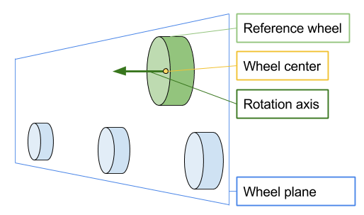
The wheel plane defined by the reference wheel.
When a Track is selected each Wheel in the Track is visualized as a wireframe cylinder showing the location and radius of the Wheel, and an arrow showing the rotation axis. Different types of Wheel Models, see below, have different color.
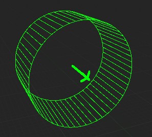
A Wheel being visualized when the owning Track is selected.
A Wheel can be one of three Models: Sprocket, Idler, and Roller. A Sprocket or an Idler, rendered in red and blue, respectively, in the Track Visualization, is a wheel that models a physical wheel that is geared into the track threads, meaning that it cannot slip. This is achieved in the simulation by merging the Track nodes with the Wheel as they pass by. There are therefore no frictional contacts between these Wheels and the Track. A Roller is a Wheel that has regular frictional contacts with the Track nodes.
A Wheel must have an associated Rigid Body that define the shape and position of the Wheel.
A Rigid Body is assigned to a Wheel by setting the Rigid Body property pair of the Wheel to the Actor owning the Rigid Body, for the Owning Actor property, and the name of the Rigid Body, for the Rigid Body Component property.
When the selected Track is an instance in a level then the Owning Actor can be set to any Actor in the same level.
Set the Owning Actor to None to search in the Actor that owns the Track.
When the selected Track is part of an Actor Blueprint then the Owning Actor property will always be None because it is not possible to reference an Actor instance in a level from a Blueprint.
In this case the Wheel must reference a Rigid Body within the Blueprint, unless the Rigid Body reference is overridden on an instance of the Blueprint by a level designer.
19.5. Rendering a Track
There are two types of rendering available for a Track. The first is a built-in editor-only Component Visualizer that renders Track nodes as black wireframe boxes with coordinate axes in them and wheels as cylinders colored by their model type. This visualization is useful for creating, configuring, and debugging Tracks, but it cannot be used as the main rendering in packaged applications because Constraint Visualizers are not available outside the editor.
Editor-only Component Visualizer for Track Component. Not available in packaged applications.
Track is agnostic to the form of rendering used to render it. It proves accessor functions for finding the size and current position of each track node to be used by a renderer to render each node. It is up to any particular renderer to decide what to do with that information. The plugin does include an example renderer tha places a Static Mesh at each Track node. That renderer can be used either as-is or as an inspiration for a custom renderer better suited for a particular application’s needs.
19.5.1. Track Renderer
The plugin includes an example Track renderer named AGX_TrackRenderer.
This is an Actor Component that should be added as an attachment child to the Track that is to be rendered.
The Track Renderer is-a Hierarchical Instanced Static Mesh Component and will create, position, and scale an instance of a Static Mesh for each Track node.
The Static Mesh to instantiate is selected with Details panel > Static Mesh > Static Mesh.

Track rendered with the Track Renderer.
19.5.1.1. Mesh Scaling and Offset
By default the Track Renderer will scale the Static Mesh to fit within the size of each Track node. To do this the renderer needs to know the size of the Static Mesh. It is common that the visual representation of one Track node should overlap with that of the neighboring Track nodes. For this reason the Track Renderer doesn’t simply scale the Static Mesh so the bounding box fit within the size of the Track node. Instead the designer can specify the local minimum and maximum points of the bound in the Static mesh that should fit within the Track node bounds. By setting this bound smaller than the size of the entire Static Mesh overlapping render meshes are produced. An offset is computed and applied to place the local mesh bounds centered inside the Track node volume.
Alternatively, instead of specifying the size of the Static Mesh it is possible to directly set the Static Mesh scale and offset.
Switch between automatic scale and offset and manual scale and offset with the Auto Scale And Offset checkbox in Details panel > Static Mesh > Auto Scale And
19.5.1.2. Updating Visual Representation
By default the Track Renderer updates the rendering state as soon as an in-editor change is detected on the Track. For Tracks with a large number of nodes this can make modifying settings sluggish. Automatic render state updates for a Track can be disabled by unchecking Track > Details panel > AGX Track Debug Visual > Auto Update Track Preview. After making some changes the new track can be visualized by either re-enabling Auto Update Track Preview again, clicking the Update Preview Data in the Track’s Details panel, or the Update Visual button in the Track Renderer’s Details panel.
19.6. Troubleshooting
19.6.1. The Tracked Vehicle is Bumpy Even on Flat Ground
This can happen when merged segments aren’t split around Rollers where the Track transition into or out of being in contact with the ground. Enable Track > Details panel > AGX Track Wheels > Split Segments on any Roller around which the Track changes direction.
19.6.2. Track Explodes When Contacts the Ground
This can have many causes. Common are too high Track > Details panel > AGX Track > Initial Distance Tension, Track Properties values that are too soft or too weakly attenuated for the current vehicle setup, or too high Restitution on the Contact Material between the Track and the ground. It is recommended to set the restitution to zero. Friction coefficient and viscosity on the Contact Material can also affect stability.
19.6.3. The Track Slips
This is often caused by improperly configured Contact Material between the Track and the ground. While each scene setup has its own optimal parametrization, a recommended starting-point is to use a Contact Material with Direct or Direct & Iterative Contact Solver, Contact Reduction enabled, a Track friction model, and Restitution set to zero. Also ensure that the Contact Material is for the correct Shape Materials, and that those Shape Materials have been assigned to the Track and the ground, and that there is a Contact Material Registrar, either as an Actor or a Component in the level that activates that Contact Material. When using one of the older Oriented Friction Models on a Contact Material also check that the Oriented Friction Reference Frame Component is set to the name of the main body of the vehicle, and if the Contact Material Registrar is not owned by the same Actor as the Track then Oriented Friction Reference Frame Actor should be set to the Actor that owns the main body.
19.6.4. The Vehicle Cannot Turn
In order for a tracked vehicle to turn smoothly it is important that the Contact Material between the Track and the ground has lower friction coefficient and higher surface viscosity in the sideways direction compared to the forward direction. This is configured in the Friction section of the Contact Material’s Details panel. Enable Secondary Friction Coefficient and Secondary Surface Viscosity and set them lower and higher, respectively, than their primary direction counterpart. When using one of the Track friction models no reference frame setup is needed. When using an Oriented Friction Model, also set Primary Direction to the forward direction of the vehicle, typically along the X axis in Unreal, and specify the reference body in the two Oriented Friction Reference Frame properties. Note that there must be one Contact Material per vehicle when using an Oriented Friction Model since a reference body must be selected per vehicle.