15. Terrain
An AGX Terrain is a deformable height field along with a symmetric 3D grid data structure that is used to simulate earth moving operations. Special rigid bodies called Shovels are used to deform the Terrain and spawn Soil Particles. An AGX Dynamics for Unreal terrain is created from an Unreal Engine Landscape. More details about the terrain model can be found in the Terrain chapter of the AGX Dynamics user manual.
Try out the Terrain level, included in the Tutorial Hallways Demo Project
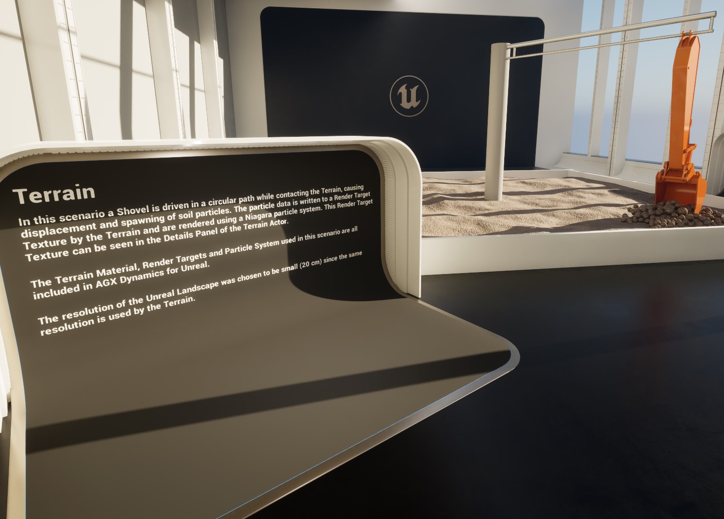
The Terrain level of the Tutorial Hallways demo project.
15.1. Creating And Configuring A Terrain
15.1.1. Creating A Landscape
The first step in creating a Terrain is to create an Unreal Landscape. There is a one-to-one correspondence between Landscape quads and Terrain cell columns in the 3D grid.
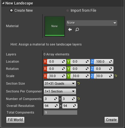
Settings when creating a new Landscape.
For more information, see the Creating Landscapes page of the Unreal Engine documentation.
The first entry in the Landscape creation dialog is Material, which is the rendering material to use.
You can use any Landscape rendering material, but be aware that deformations done to the Terrain are not reflected back onto the source Landscape.
Instead the height changes are made available in a displacement map which can be used in a Landscape rendering material to apply a world offset to each Landscape vertex.
AGX Dynamics for Unreal ships with an example material, M_DeformableLandscapeBase, that demonstrate the technique.
If this material is not visible, see AGX Dynamics for Unreal content not showing.
The scale in the X and Y directions set on the Landscape becomes the size of the Terrain cells in cm, which in turn define the nominal size of the soil particles spawned around shovels. A smaller scale in these directions result in a higher resolution simulation at the cost of a higher computational load. Some experimentation may be required to find a good tradeoff between resolution and simulation performance. The Z scale define the range and precision of the Landscape height offsets.
The Section Size, Sections Per Component, and Number of Components properties specify the internal layout of the Landscape. AGX Terrain is only concerned with the final number of quads, i.e., the Overall Resolution field.
15.1.2. Creating an AGX Terrain Actor
With the Landscape created the next step is to create and configure the Terrain. AGX Terrain is an Actor that can be found in the AGX tab of the Place Actors panel, and the AGX submenu of the Quick Add drop-down in the main tool-bar.
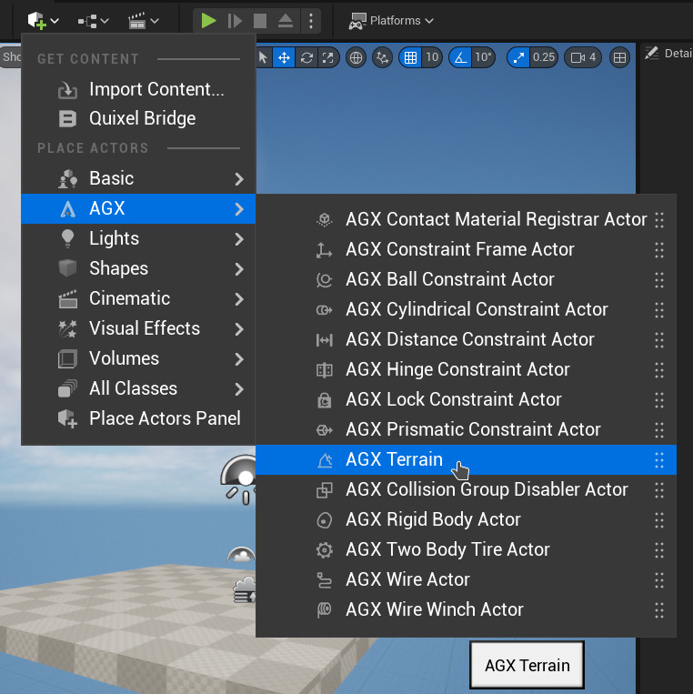
Adding an AGX Terrain Actor from the Quick Add drop-down.
It has the following simulation related properties in its Details panel:
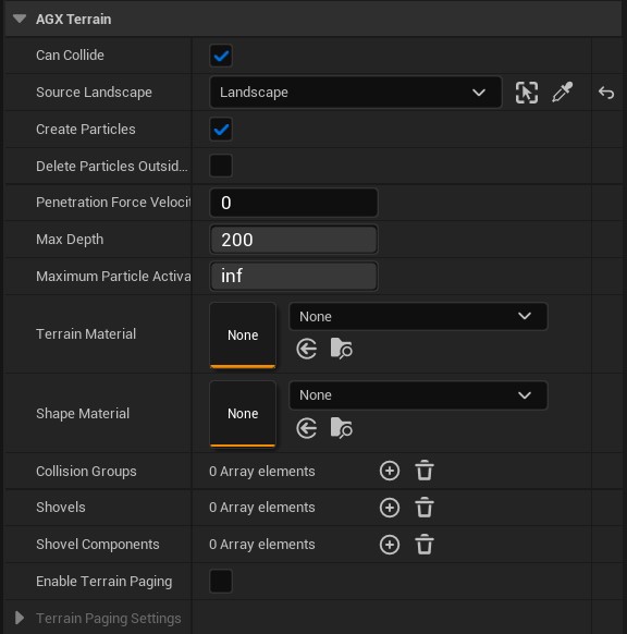
The Source Landscape property is set to point to the Landscape that the Terrain should be associated with and initialized from.
15.1.3. Terrain Bounds
Once a Source Landscape has been selected, the Terrain bounds can be seen in the viewport:
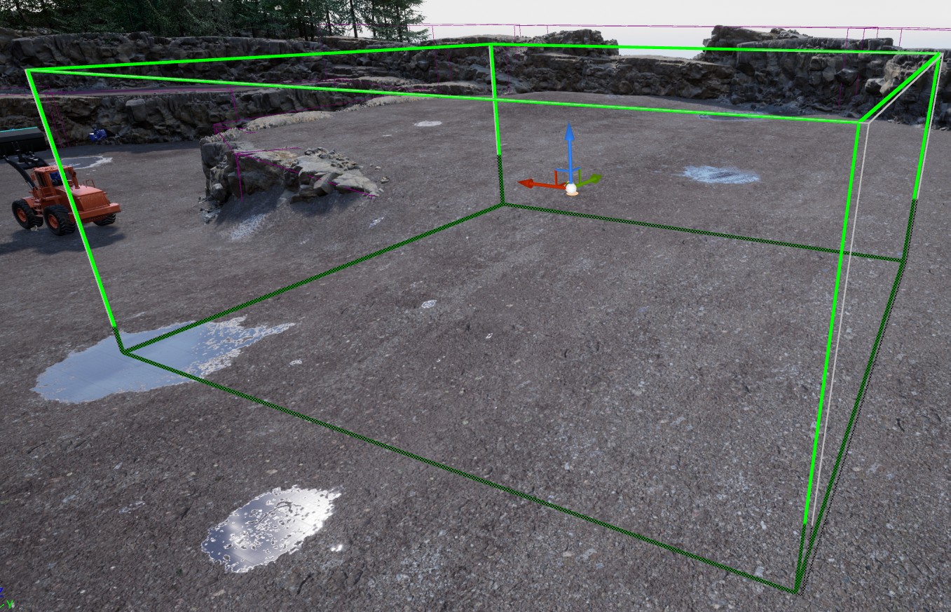
The bounds of the Terrain determines it’s overall size.

The size of these bounds can be changed by editing the Half Extent property in the Details panel of the Terrain, and the position is changed by moving the Terrain Actor.
The thinner, gray box, indicates the exact currently selected bounds according to the Half Extent.
The green box indicates the Terrain’s final size and will always align with the Landscape’s grid lines.
It will expand with the thinner, gray box, so that is as large as possible, but strictly within it.
Enable Infinite Bounds to have the Terrain cover the entire Landscape.
The underlying AGX Dynamics Terrain will always be positioned such that it lies in the plane of the selected Landscape at Begin Play. Therefore, the Z-component of the Terrain Actor’s location and the Terrain bounds are not used.
15.1.4. Terrain Properties
The Terrain Properties Asset stores general properties for the AGX Terrain. Here, features and behavior of the AGX Terrain can be modified, enabled or disabled. The Terrain Properties Asset is assigned in the AGX Terrains Details Panel.
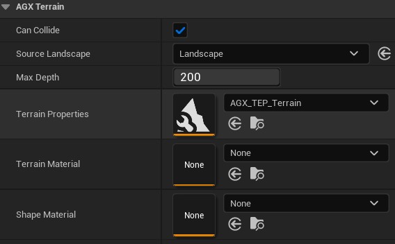
Terrain Properties in the Terrains Details Panel.
See the Terrain Properties chapter of the AGX Dynamics user manual for more details.
Multiple AGX Terranis can share the same Terrain Properties Asset. If no Terrain Properties Asset is assigned to an AGX Terrain, default Terrain Properties will be used.
15.1.5. Terrain Material
A Terrain Material describes the Terrain bulk properties of the Terrain (whereas a Shape Material describes it’s surface properties). See the Terrain Material Configuration chapter of the AGX Dynamics user manual for a complete list and a description of each.
AGX Dynamics include a library of calibrated Terrain Materials and these are available in AGX Dynamics for Unreal through assets found in the AGXUnreal Content folder in the Content Browser.
They are accessed either by navigating the Content Browser to AGXUnreal Content > Terrain > TerrainMaterialLibrary or by entering the search string “Terrain Material Library” in the Terrain Material property drop-down menu.
If these materials are not visible, see AGX Dynamics for Unreal content not showing.
The View Options option Search Asset Path must be checked in the property drop-down menu for the Terrain Material Library materials to show up.
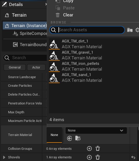
Finding materials in AGX Dynamic’s Terrain Material Library.
The Terrain Material Library materials should not be edited, any edits made will be lost the next time the Unreal Engine material library is synchronized with the AGX Dynamics library. To created modified version of these materials create a copy of the library material, place it outside of the material library folder, and edit the copy.
The Terrain tab of the AGX Dynamics Mode contains a button to refresh the Terrain Material Library, making it possible discover new Terrain Materials added to the AGX Dynamics Terrain Material Library.
The surface properties of the Terrain is described by a Shape Material that can be assigned to the Terrain, see Materials for more details about Shape Materials.
15.1.6. Shovels
Shovels are things that can dig in a terrain. There are two Shovel implementations: Shovel Component and the deprecated Shovel. Shovel Component encapsulates most Shovel settings into a single Component, while the deprecated Shovel spread the properties out over multiple Components and the Shovels list in the AGX Terrain Actor. It is recommended to update any Shovel of the deprecated type and instead use a Shovel Component.
15.2. Creating a Shovel
In AGX Dynamics a Shovel is a description of how a Rigid Body interacts with an Terrain. The description consists of four pieces of information: a top edge, a cutting edge, a cutting direction, and a bundle of parameters. For more information on Shovels in AGX Dynamics, see the Shovel section of the Terrain chapter of the AGX Dynamics user manual
In AGX Dynamics for Unreal a Shovel is a Component that identifies a Rigid Body Component as being a Shovel and that has properties for the four pieces of information. The edges and the direction are specified as Frames, two for the edges and one for the direction, and the bundle of parameters is an asset named Shovel Properties.
The following image shows what a simple shovel consisting of two boxes may look like, with the edges and direction visualized as white, red, and green lines.
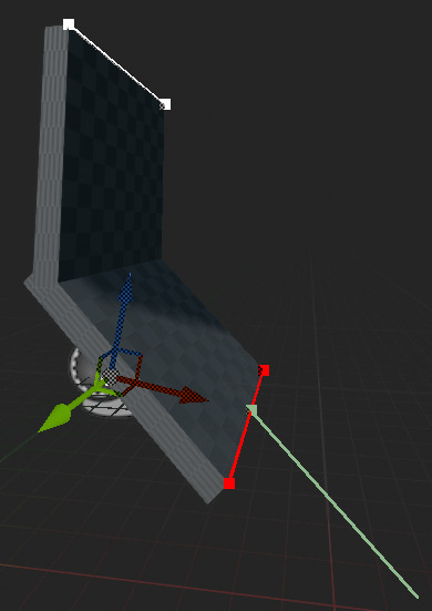
A shovel built from two boxes. The lines indicate, from top to bottom: the top edge (white), the cutting edge (red), and the cutting direction (green).
15.2.1. Shovel Component
Details panel for the Shovel Component:
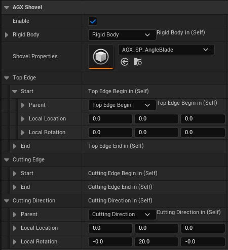
Details panel for a Shovel Component.
The Enable flag turns shovel behavior on and off. The AGX Dynamics representation of the Shovel is still created even when the flag is off.
The Rigid Body that should be imbued with shovel behavior in the simulation is pointed-to by the Rigid Body property. No changes need to be made on the Rigid Body Component, all configuration is done within the Shovel Component. Only a single Shovel is supported per Rigid Body.
The Shovel Properties is a reference to an asset in the Content Browser. For more information see Shovel Properties below.
15.2.2. Frames
The Top Edge and Cutting Edge are used to describe the geometry of the shovel. The Cutting Direction is the intended direction of motion of the shovel when digging, often parallel to the bottom plate. The edges and the direction are specified using Frames. A Frame is a tool for identifying a frame of reference relative to a Scene Component, such as a Rigid Body or an Observer Frame.
15.2.3. Top- and Cutting Edge
An edge consists of a Start Frame and an End Frame. To define the Top Edge of a Shovel set Top Edge > Start > Parent to the Scene Component that the edge should be on. This is often the Shovel’s Rigid Body, a Shape on that Rigid Body, or an Observer Frame. The position can be fine-tuned using the Local Location property, or by clicking the handle in the viewport and moving it with the transform gizmo.
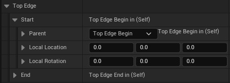
The Top Edge part of the Details panel for a Shovel Properties asset. In this case the Parent has been set to reference an Observer Frame specifically created and positioned for this purpose. Therefore the Local Location can be left at zero.
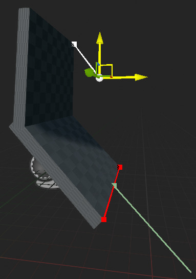
Moving the Top Edge start handle using the transform gizmo.
Local Rotation is not used by edges, but it is used by the Cutting Direction.
The Cutting Edge is configured in very much the same way as the Top Edge.
15.2.4. Cutting Direction
For the Cutting Direction there is only one Frame since a direction doesn’t have an extent. The rotation of the Frame defines the Cutting Direction, with zero rotation being the local X axis in the Frame’s selected parent Component. Rotate the Cutting Direction by either editing the Local Rotation numbers in the Details panel or by selecting the handle in the viewport and rotating the transform gizmo. The location of a direction doesn’t matter, only the rotation is significant. It is however still possible to change the location since the direction may be easier to set correctly when the visualization is drawn next to some related Shape in the Shovel.
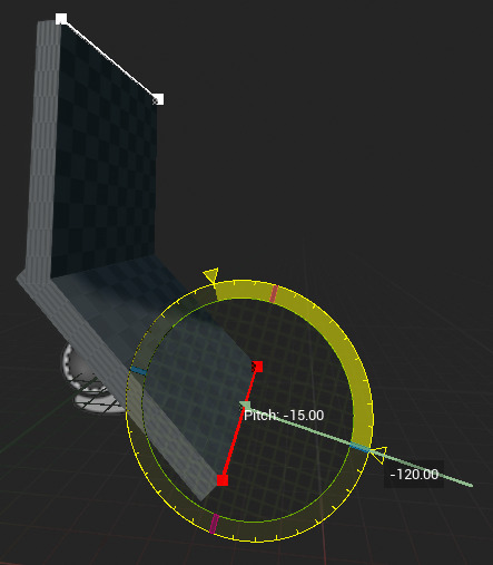
Rotating the Cutting Direction.
You can read more about how the edges and the direction should be set in the Shovel Setup section of the Terrain chapter of the AGX Dynamics user manual.
15.2.5. Setting Edges and Direction in Blueprint
The edges and direction implementation is been designed for easy configuration in the Details panel, but it is also possible to set and modify them using Blueprint scripts. The edges and direction object hierarchy is implemented as structs, which are treated in a special way in Blueprints. While it is possible to call Set Top Edge on a Shovel Component, this requires the creation of a complete AGX Edge object from scratch. The recommended approach is instead to use the Set Members node to directly manipulate the struct members and then call Finalize Shovel Edit to commit the new values to the AGX Dynamics state. Multiple edits can be committed with a single Finalize Shovel Edit. Finalize Shovel Edit is only required when modifying one of the following Shovel properties using Set Members nodes:
Top Edge
Bottom Edge
Cutting Direction
The following Blueprint script demonstrates how to update set the location of the top edge’s start frame, and includes a place-holder for updating any other edge or direction frame.

Configuring edges and direction in Blueprint script.
15.2.6. Shovel Properties
Most of the configuration of a Shovel is made using a Shovel Properties asset. A new Shovel Properties asset is created from the Content Browser’s right-click context menu, where it can be found under the AGX Dynamics > Terrain submenu.
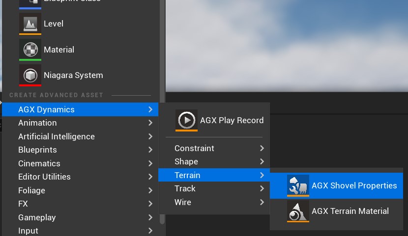
Creating a Shovel Properties asset from the Content Browser.
By convention, Shovel Properties assets are named with a AGX_SP_ prefix.
The Shovel Properties asset contains a large number of properties. See the Terrain chapter of the AGX Dynamics user manual for a description of how they are used, and the agxTerrain::Shovel API Reference for a description of each one.
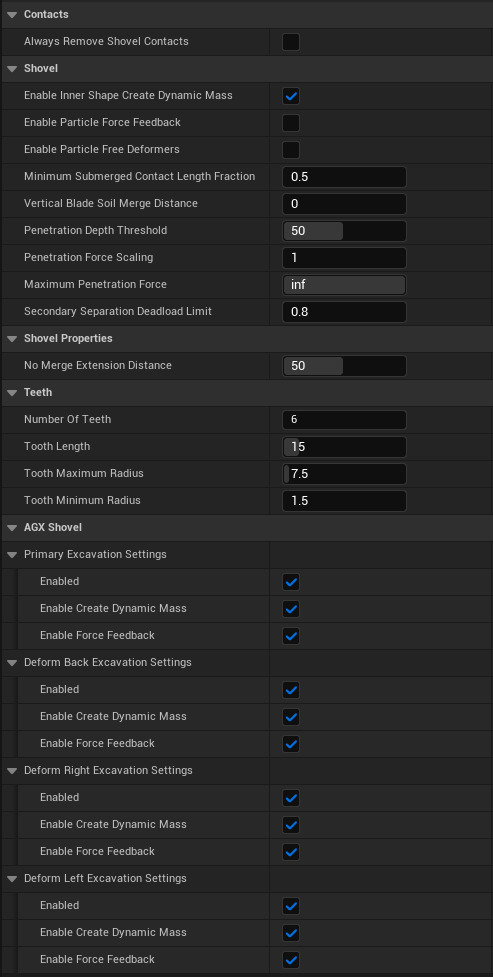
Details panel for a Shovel Properties asset.
15.2.7. Video Demonstration
Note
In the video below, the Shovel Component is added to the Terrain Actor. This is no longer needed since all Shovel Components now add themselves to the Simulation at BeginPlay.
15.3. Import Terrain Limitation
Currently, a Terrain or Height Field can not be imported from an AGX Dynamics archive (.agx).
It is possible to import Shovels, but beware that imported Shovels are not automatically reigstered with any Terrain Actor.
More information about import limitations can be seen in Models With no Import Support.
15.4. Terrain Rendering
Terrain rendering consists of two parts: height-field and particles. The height-field is the surface of the Terrain and is deformed when a shovel moves through it or a heavy load compacts the soil. Particles are generated by AGX Dynamics when a shovel interacts with the Terrain. The particle data is broadcast by the Terrain via Delegates, and is typically rendered by one or several Particle Rendering Components. The Terrain Actor comes with a default particle rendering Component, but other types of Rendering Components, either provided by AGX Dynamics for Unreal or a user, can be used.
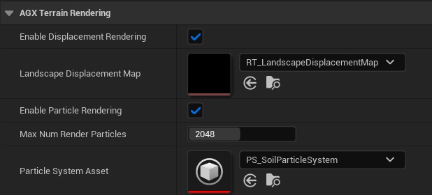
The Terrain Actor also provides read-only access to height-field data through the render target Landscape Displacement Map.
This render target have some requirements on it.
See subsections below and the example assets in AGXUnreal Content/Terrain/Rendering/HeightField/RT_LandscapeDisplacementMap and AGXUnreal Content/Terrain/Rendering/Particles for details.
These can be used in your Levels, but if you have multiple AGX Terrains then each terrain instance should have its own Landscape Displacement Map.
The vieo below demonstrates how to use a custom Render Material with AGX Terrain.
15.4.1. Landscape Displacement
The AGX Terrain Actor doesn’t provide any rendering by itself. Instead the intention is that the source Landscape should provide the visual feedback.
AGX Terrain writes height-field displacements to the render target selected for Landscape Displacement Map.
The render target is filled with the height displacement of each vertex, i.e. how much each vertex has been moved up or down from the initial state.
This data can be used to do drive World Position Offset in the Landscape’s render material.
The render target must have a size matching the overall vertex resolution of the Terrain.
The Terrain will attempt to resize the render target if necessary on Begin Play.
The render target should have the following additional settings:
Property |
Value |
|---|---|
Mip Gen Settings |
NoMipmaps |
LOD Bias |
0 |
Texture Group |
RenderTarget |
Address X |
Clamp |
Address Y |
Clamp |
Render Target Format |
RTF R16f |
An example terrain rendering material is provided with the plugin, stored in AGXUnreal Content/Terrain/Rendering/HeightField.
It uses the height displacement map to apply a World Position Offset to the Landscape vertices.
By default the example material reads displacements from the render target at AGXUnreal Content/Terrain/Rendering/HeightField/RT_LandscapeDisplacementMap.
If you have multiple AGX Terrains then each should have its own render target, and the DisplacementMap parameter of the material instance for each terrain should be set to the correct render target.
The example material must know the size and position of the Landscape to know where in the displacement render target each vertex should sample from.
The information is provided to the Landscape’s material through material parameters set by the Terrain.
For this to work the material must have parameters with the correct names and Use Dynamic Material Instance must be enabled on the source Landscape.
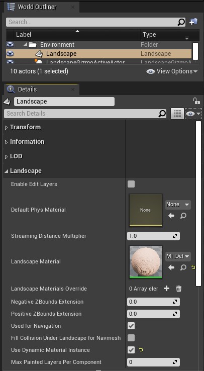
Enable Use Dynamic Material Instance on the source Landscape to enable automatic material parameter setting.
If you cannot enable Use Dynamic Material Instance then another alternative is to create a Material Instance and manually set the material parameters.
The parameters are:
Parameter |
Description |
|---|---|
LandscapePositionX |
The lowest X coordinate of the Landscape. Often the X coordinate of the Landscape Actor’s Location. |
LandscapePositionY |
The lowest Y coordinate of the Landscape. Often the Y coordinate of the Landscape Actor’s Location. |
LandscapeSizeX |
The length of the Landscape along the X direction, in cm. |
LandscapeSizeY |
The length of the Landscape along the Y direction, in cm. |
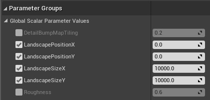
The material parameters available on the Deformable Landscape render material.
The plugin provide the material function LandscapeSpanningUV that returns the texture coordinate in the displacement map for the current vertex.
Feed this coordinate to the UVs input pin of a Texture Sample node that samples from the displacement map and use the red channel from the sample to set the Z coordinate of World Position Offset.
Additional transformations is required if the Landscape is rotated.
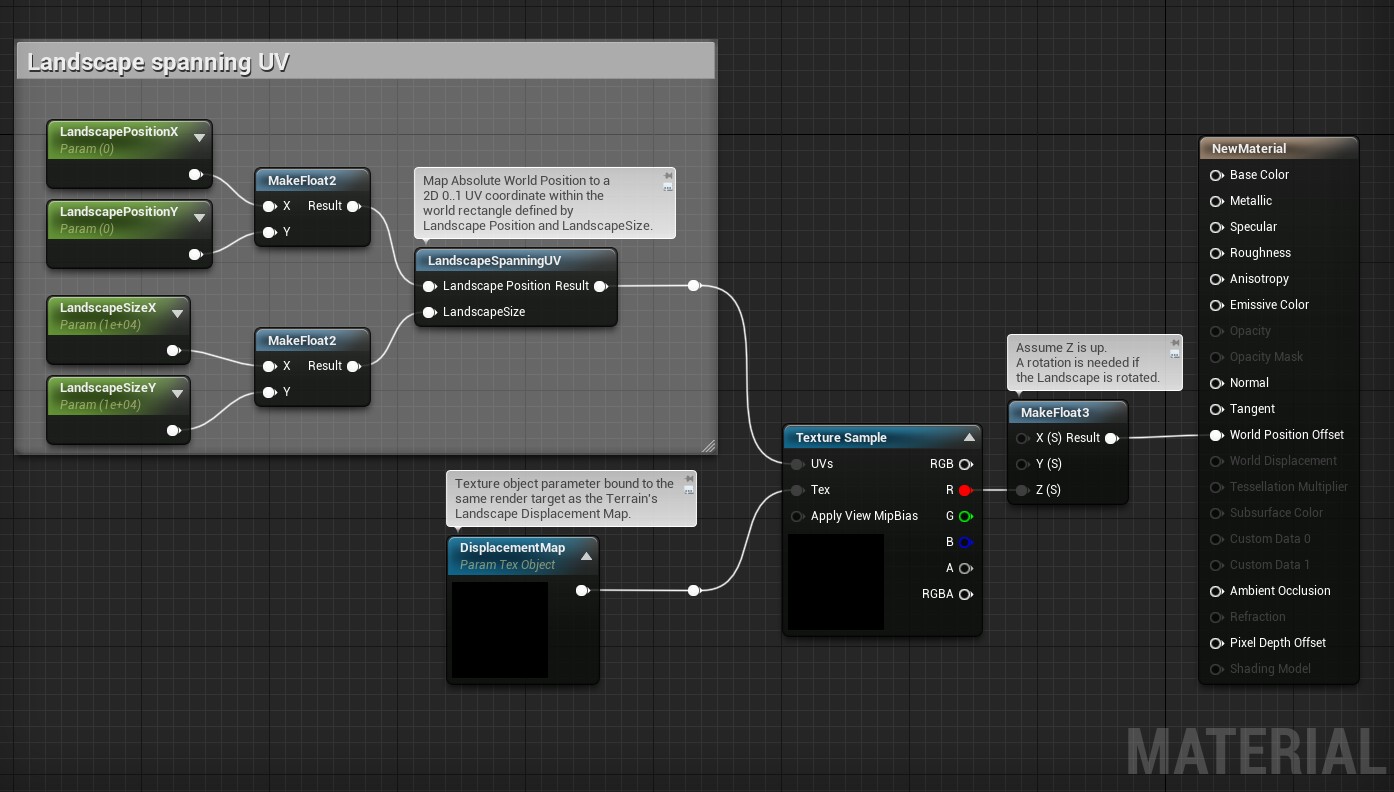
The material parameters are used to determine where on the displacement map to sample from.
The displacement can also be used to drive other rendering effects, such as using a darker color for small negative displacements to make tire tracks more visible.
15.4.1.1. Limitations Of the Example Landscape Material
A limitation of the example Landscape material is that the Landscape Actor’s Location must be in the minimum corner of the Landscape. This is the default configuration when creating a new Landscape in the Landscape Mode. Extra Landscape Components added on the negative side, in either direction, of the Landscape location will not be rendered correctly.
Another limitation is that rotated Landscapes cannot be rendered correctly.
15.4.2. Particle Rendering Components
The soil particles created when a shovel moves through the terrain are typically rendered by one or several particle rendering Components. These in turn often does the rendering with a Niagara particle system.
Data for each particle is communicated from Terrain Actor to any listening particle rendering Components via the OnParticleData Delegate provided by the AGX Terrain Actor.
This Delegate passes a struct FDelegateParticleData that contains data, such as position, radii, velocity and more, for all known particles.
15.4.2.1. Default Particle Rendering Component
The Terrain Actor has a default particle renderer Component of type UAGX_SoilParticleRendererComponent, included in AGX Dynamics for Unreal, which can be seen in the Terrain Actors Components list:
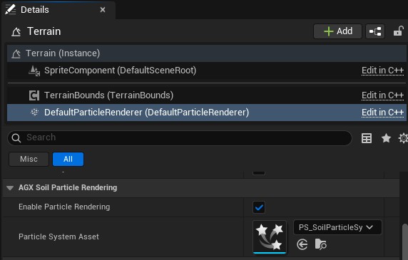
The default particle renderer Component in a Terrain Actor.
This particle rendering Component gets particle data from the Terrain Actor and uses the built in Niagara Particle System Asset at AGXUnreal Content/Terrain/Rendering/Particles/SoilParticleSystem/PS_SoilParticleSystem to do the rendering.
This in turn is done by writing to certain Niagara buffers using the Niagara Data Interface from C++.
15.4.2.2. Upsampling Particle Rendering Component
Apart from the default particle renderer, AGX Dynamics for Unreal also provides the Upsampling Particle Renderer Component. This uses a more advanced scheme to upscale the number of particles rendered, which is done on the GPU in custom shaders.
This is based on the implementation from the thesis work Comparison of the Practical Integration of Particle Upsampling in Two Game Engines: Unity and Unreal Engine. To use the Upsampling Particle Rendering Component, simple disable the default particle rendering Component and add an Upsampling Particle Rendering Component to the Terrain Actor:
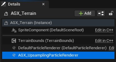
Adding a Upsampling Particle Rendering Component to a Terrain Actor.
Note
To avoid double-rendering of particles, the default particle rendering Component of the Terrain Actor should be disabled.
The Upsampling Particle Rendering Component does upsampling in custom shaders on the GPU and then uses the Niagara System Asset in Niagara Particle System Asset at AGXUnreal Content/Terrain/Rendering/Particles/UpsamplingParticleSystem/PS_UpsamplingParticleSystem to do final rendering.
It is recommended to copy the Niagara System Asset to your own project before modifying it.
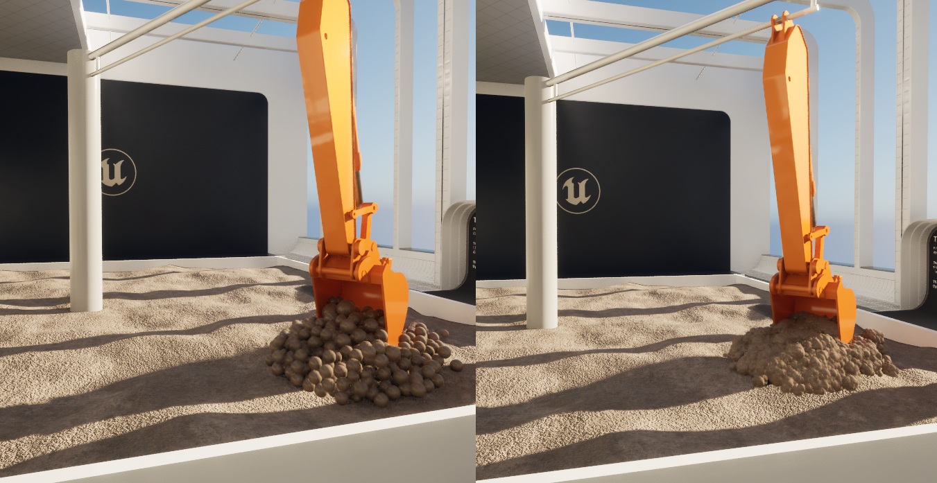
An example of using the default rendering (left) and particle upsampling (right).
The upsampling behavior of the Upsampling Particle Rendering Component can be modified from it’s Details Panel:
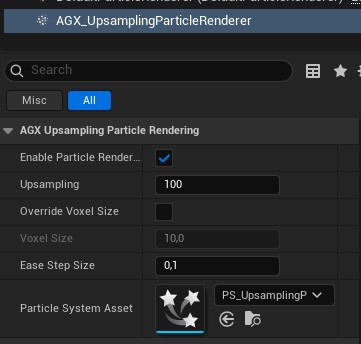
The Details Panel of the Upsampling Particle Rendering Component.
15.4.2.3. Custom Particle Rendering Component
As a user, it is possible to write your own Particle Rendering Components.
The strategy for this is to listen to the OnParticleData Delegate provided by the AGX Terrain Actor, and using that data to render the particles in some way.
To se examples of this, see either the Soil Particle Renderer Component or the Upsampling Particle Renderer Component.
Note
To avoid double-rendering of particles, the default particle rendering Component of the Terrain Actor should be disabled.
15.4.3. Troubleshooting
15.4.3.1. Landscape not Being Displaced
Check that the AGX Terrain has Enable Displacement Rendering checked.
Check that the AGX Terrain has a compatible render target assigned to
Landscape Displacement Map.- Check that the Landscape has a Material Instance that supports Terrain Displacement.
I.e. that it reads texture samples from the displacement map and passes to the World Position Offset pin.
Check that the Material Instance has the Displacement Map parameter set to a the same render target at
Landscape Displacement Mapon the AGX Terrain.- Check that the Material Instance has the Landscape Size and Landscape Position parameters set correctly.
Either by enabling
Use Dynamic Material Instanceon the Landscape so that AGX Terrain can set the parameters.Or by setting the parameters manually on the Material Instance.
- Check that the Render Target has been configured properly.
See table in Landscape Displacement.
15.5. Open World Landscape
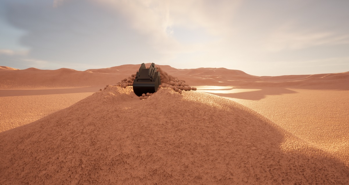
Digging in an Open World Landscape.
Using Terrain with Open World Landscapes works the same way as for regular Landscapes,
but there are some caveats.
One thing to note is that the Landscape Material used should be assigned to each Landscape Streaming Proxy.
This is easiest done by multi-selecting them in the World Outliner and assigning the Material in the Details panel.
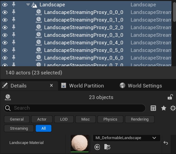
Assigning Material to all Landscape Streaming Proxies.
For the Terrain to be initialized correctly on Begin Play it needs access to the Landscape Streaming Proxies in and near the Terrain bounds.
This means that the proxies must already have been be loaded during Terrain initialization.
This can be ensured either by disabling streaming completely in World Settings panel,
or on individual proxies by disabling Is Spatially Loaded.
Terrain tries to detect proxies that should have Is Spatially Loaded disabled and logs a warning about them in the Output Log during Play In Editor sessions.
The detection cannot be performed in packaged applications because it relies on editor-only functionality.
The effect of not-yet-loaded streaming proxies in a packaged application is no collisions between the Terrain and other objects in the level.
Since Landscape cannot be spatially loaded and Unreal Engine does not allow a spatially loaded Actor to reference a non-spatially loaded Actor, Terrain must also be non-spatially loaded.
This means that the Actor owning any Shovel referenced by the Terrain must also be non-spatially loaded.
As with non Open World Landscapes, the resolution of the Terrain is bound to the resolution of the Landscape.
To enable high resolution deformations, the overall resolution (XY scale) of the Landscape should be selected accordingly.
It is recommended to use the Terrain Bounds to reduce the size of the underlying Terrain when working with Open World Landscapes since they typically hold large amounts of vertex data.
15.6. Terrain in Blueprint
The AGX Terrain is an Actor class, which makes working with an AGX Terrain inside a Blueprint as easy as creating a new Blueprint class and selecting the AGX_Terrain as parent.
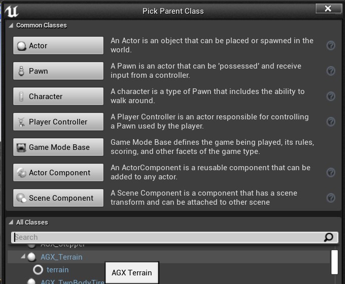
Creating a new Blueprint class with AGX_Terrain as parent.
After creation, AGX Terrain properties may be accessed from the Details panel or Event Graph as usual.
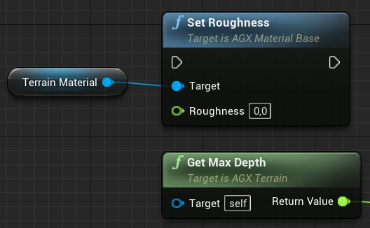
Accessing AGX Terrain properties from the Event Graph.
15.7. Terrain Paging
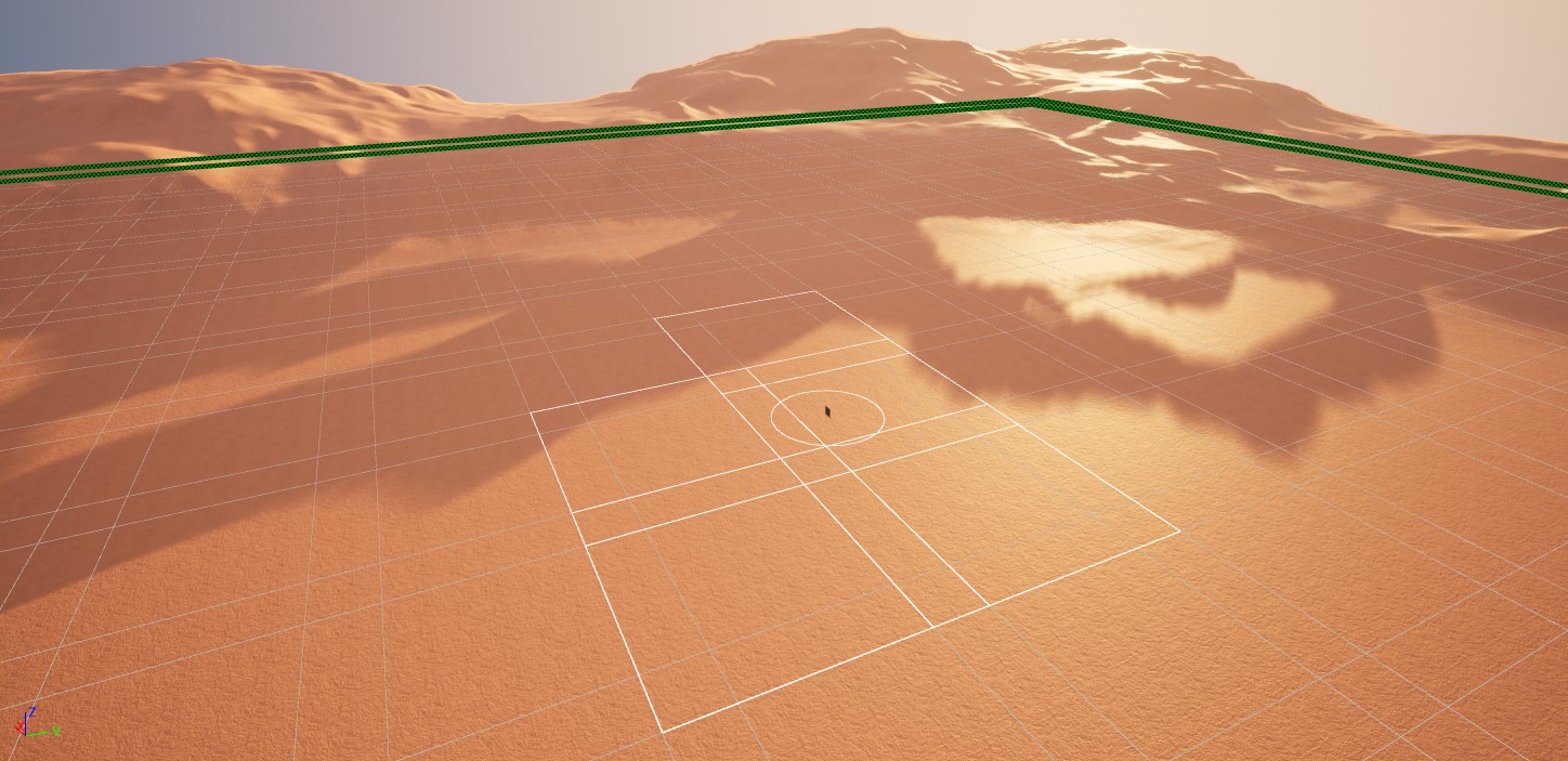
Terrain Paging in an Open World Landscape.
Terrain Paging allows a large Unreal Landscape to be split into multiple simulated Terrain tiles. The tiles are lazily loaded automatically when they are needed and are paged out to disk when they are not. This is useful when a large Landscape should be simulated with fine-grained resolution, which would result in unmanageable data sizes using the standard Terrain.
Terrain Paging can be used for both Open World Landscapes and non Open World Landscapes.
Terrain Paging in AGX Dynamics for Unreal uses AGX Dynamics Terrain Pager to perform the automatic loading and unloading of Terrain tiles. Read more about the AGX Dynamics Terrain Pager in the AGX Dynamics user manual.
Note
The Terrain Paging in AGX Dynamics for Unreal does not affect loading and unloading of Unreal World Partitioning regions.
15.7.1. Enabling Terrain Paging
Terrain Paging can be enabled by checking the Enable Terrain Paging setting in the Details panel of the Terrain actor.
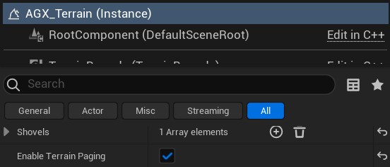
Enabling Terrain Paging.
15.7.2. Terrain Paging Settings
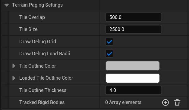
Terrain Paging settings.
The Tile Overlap is used by AGX Dynamics to ensure that the edges of two adjacent tiles match when excavation is performed around that edge.
It should be larger than both the length of the cutting edge interacting with the Terrain as well as twice the expected maximum length of a soil-wedge, which depends on how deep excavation in the Terrain will be performed.
The Tile Overlap can be seen as the narrower sections of the debug rendering of the grid in the image below.
The Tile Size is the overall side length of each tile, including overlap.
A small Tile Size means fast tile load times but may also mean more memory usage due to the overlap/side length ratio being higher.
A large Tile size may need less memory but the tile load event will take longer.
Generally, the higher the resolution of the Landscape, the smaller Tile Size should be used to ensure tile load times are kept short enough not to cause time spikes in the Simulation.
See Loading and Unloading of Terrain Tiles for more details on Terrain tile loading.
The Draw Debug Grid and Draw Debug Load Radii can be used to enable or disable debug rendering.
To enable live debug rendering of currently loaded tiles during Play, detach from the Player Controller (F8) and select the Terrain Actor in the World Outliner.
Tracked Shovels and Tracked Rigid Bodies are a lists of objects that the Terrain Pager uses to determine when Terrain tiles should be loaded and unloaded.
For more details on tracked Rigid Bodies and shovels when using Terrain Paging, see section Loading and Unloading of Terrain Tiles.
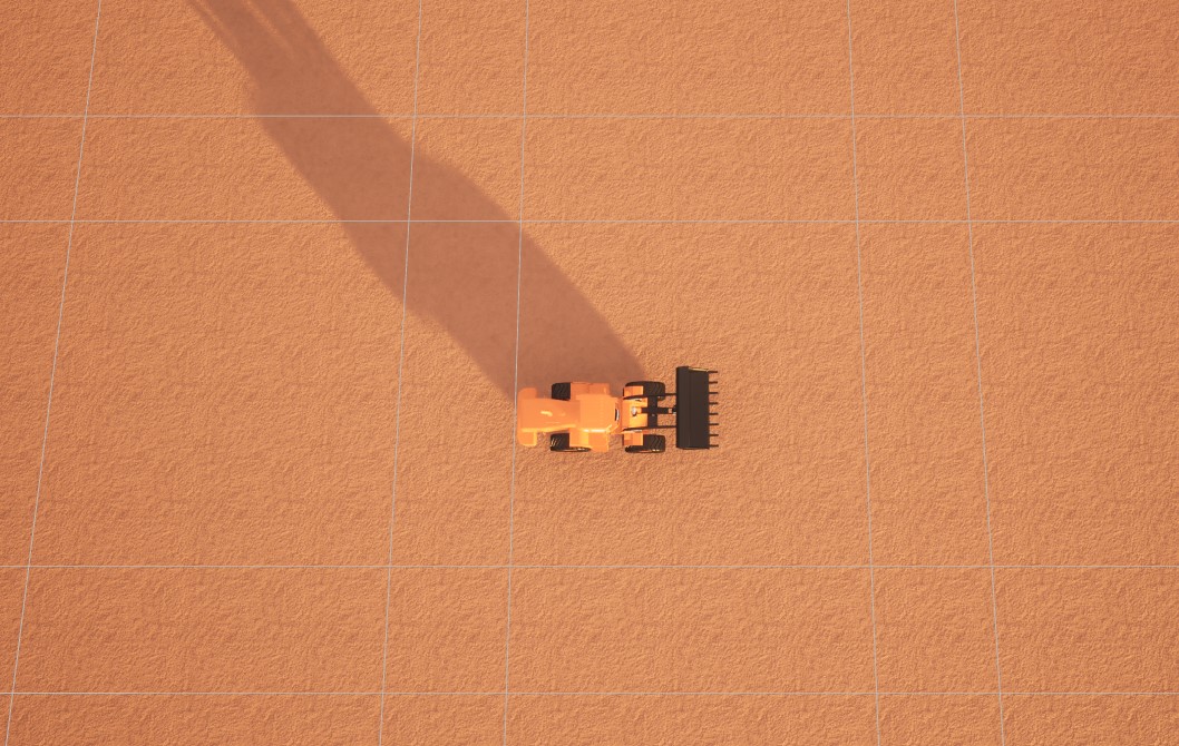
Terrain Paging tile layout (debug rendering).
15.7.3. Loading and Unloading of Terrain Tiles
When using Terrain Paging, tiles are automatically loaded and unloaded when needed.
The Terrain Pager keeps track of a list of Shovels and Rigid Bodies to determine when Terrain tiles should be loaded or unloaded.
Each Shovel and Rigid Body have a Required Radius and a Preload Radius associated with them.
When the Preload Radius of a Shovel or tracked Rigid Body goes outside the edge of a Terrain tile, heights are read from the Landscape in a background thread and are prepared for a new Terrain Tile creation.
The Required Radius tells AGX Dynamics that the tile must be loaded and existing at the time of reaching the edge of the previous Terrain tile.
To set Required Radius and Preload Radius of a tracked Shovel or tracked Rigid Body, simply specify them in the Details panel of the Terrain Actor.
For Shovels, this is set in the Tracked Shovels array of and for Rigid Bodies, this is set in Tracked Rigid Bodies in the Shovel Settings in the Details panel.
It is important to note that even though Landscape heights are read from a background thread, at the beginning of creating a Terrain tile, Step Forward may be briefly blocked due to internal threading synchronization.
This is typically a fast procedure, but if the very large Tile Size has been selected (with many vertices), it may cause simulation time spikes.
If this situation occurs, a smaller Tile Size may be chosen.
15.8. Troubleshooting
15.8.1. Flickering Particles
In some versions if Unreal Engine, particle “flickering” has been observed.
The effect is purely visual and is caused by the fact that particles often changes indices between time steps as stored in the Terrain Particles Data map, which is a result of how AGX Dynamics stores particle data between time steps.
This changing of indices is interpreted by Unreal Engine as a large velocity, since it may appear that one particle changes its position abruptly, thus causing some unwanted visual effects.
A workaround to this issue is to disable Motion Blur in the Particle Emitter in the Niagara System used by the AGX Terrain actor.
Open the Niagara System asset used by the AGX Terrain actor in the editor and select the Render section of the Particle Emitter.
From there, the Motion Blur setting can be disabled. Once disabled, compile and save the Niagara System asset.
15.8.2. No Contacts With Terrain
If objects fall through the Terrain check the following:
Has the Source Landscape been set on the Terrain?
Has the Terrain been placed correctly?
Has the Terrain’s Height Field Bounds Half Extent been set large enough?
You should see green lines outlining the area where Terrain is active when the Terrain is selected in the Outliner.
If using Terrain Paging, is the Tile Size set small enough so that an entire tile fit within the Terrain bounds, and does the tiles cover the intended area?
You should see gray lines outlining the Terrain tiles when the Terrain is selected in the Outliner.