16. Wire
AGX Wire is used to simulate wires, ropes, and chains. On the AGX Dynamics side it is a lumped element structure with dynamic resolution to maintain stability even under high tension. On the Unreal Engine side the wire is provided as a Component that contains a number of Properties for configuration, with the most important one being a list of route nodes. These define the initial route of the wire.
A Wire side, begin or end, can be attached to a Wire Winch, which is able to haul in or pay out wire, or to a Rigid Body using a Body Fixed node.
During simulation the Wire is represented by a collection of AGX Dynamics bodies, shapes, and constraints that are created and destroyed dynamically as needed. No Unreal Engine representation for these objects exist, but some information about them can be gathered through wire iterators.
Try out the Wire level, included in the Tutorial Hallways Demo Project
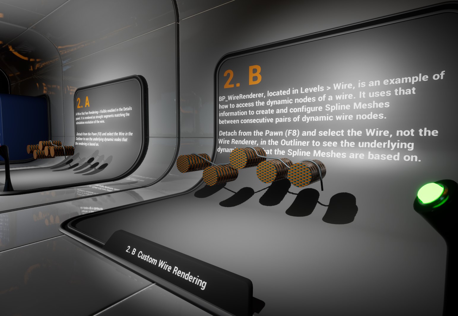
The Wire level of the Tutorial Hallways demo project.
16.1. Creating a Wire
A Wire is created by adding an AGX Wire Component to an Actor or a Blueprint. When first created the Wire’s route node list will contain two nodes. The first node in the list marks the beginning of the wire, and the last node marks the end.
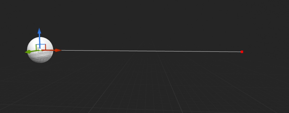
A newly created Wire in the Blueprint Editor.
The route nodes can be moved by clicking to select them and then dragging the transformation widget in the usual way.
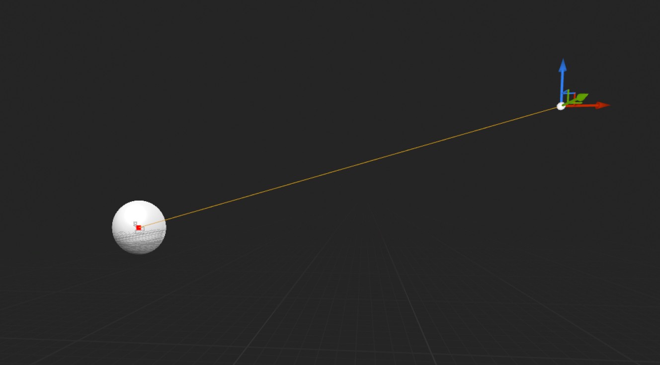
A wire route node being moved.
Deselect the route node by clicking it again.
New route nodes can be created by duplicating an existing node.
Hold Alt while dragging the transformation widget to duplicate the selected node.
The new node is always placed after the node being duplicated in the route nodes list, i.e., closer to the end side of the wire.
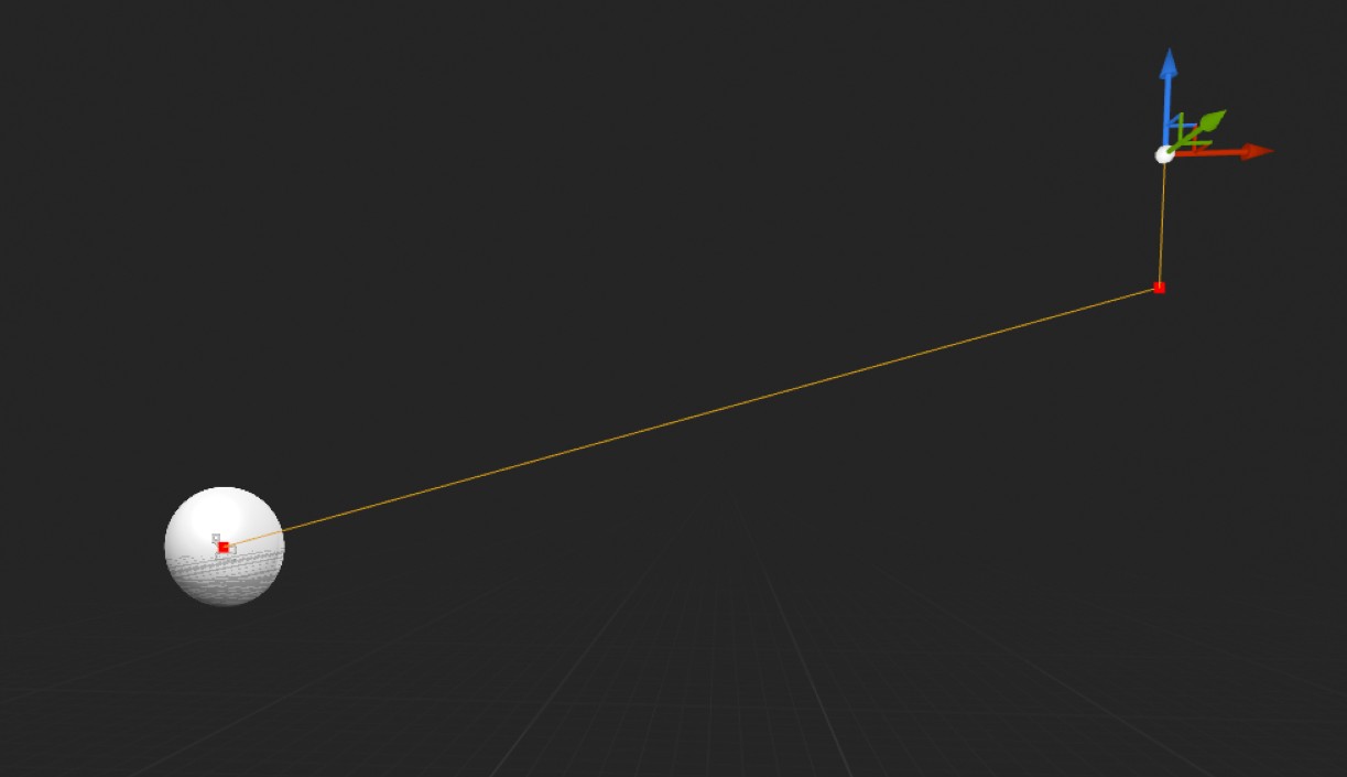
A wire route node being duplicated.
The following video demonstrates how to create and route a Wire by first positioning the second default created route node and then duplicating and positioning additional nodes to define the initial path of the Wire.
Note
A Wire Component should never be attached as a child to a Rigid Body Component.
16.2. Importing a Wire
A Wire can be imported from an existing AGX Dynamics archive (.agx). Some limitations apply in this case, which are detailed in Wire and Track Import Limitation.
16.3. Configuring a Wire
A collection of settings for the wire is displayed in the Wire’s Details panel. These settings are grouped into a number of categories. The first category, AGX Wire, contains settings for the wire as a whole.
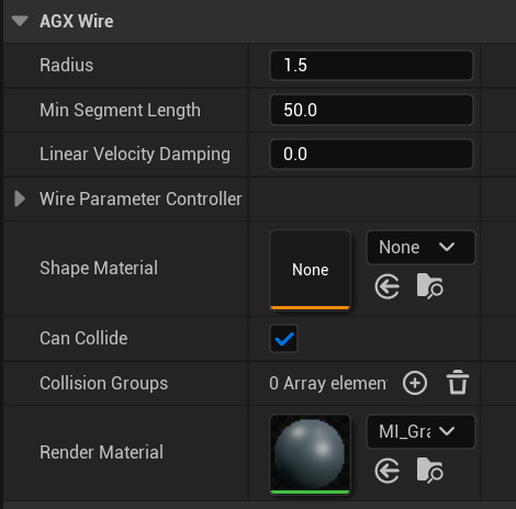
The AGX Wire category of a Wire’s Details panel.
Property |
Unit |
Description |
|---|---|---|
Radius |
\(cm\) |
The radius of the wire, in cm. |
Min Segment Length |
\(cm\) |
The shortest a lumped segment is allowed to become. |
Linear velocity damping |
\(kg \cdot s^{-1}\) |
Linear velocity damping to assign to all lumped elements of the wire. |
Shape Material |
Asset reference |
The Shape Materia to use for the wire. |
Can Collide |
Boolean |
Set to false to disable contact generation for the wire |
Collision Groups |
See Collision Groups. |
|
Render Material |
Unreal Engine Material to use for the default rendering of the wire. |
16.3.1. Wire Parameter Controller
In addition to the parameters described above, Wire contains an additional set of advanced parameters within the Wire Parameter Controller group.
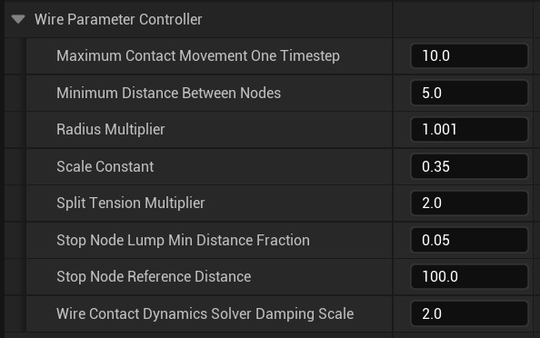
Additional wire parameters.
16.3.2. Shape Material
A Wire has a Shape Material that define the internal properties of the wire as well as how it interacts with other objects in the scene through contacts. The latter part works in the same way as for regular Shape Components, for more details see Materials. The Physical Material asset used for a Wire is of the same type as those used by regular Shapes. The internal properties of the wire are defined by the Wire section of the Shape Material.
The following screenshot shows the Wire section of an AGX Shape Material asset.
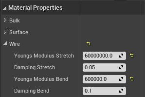
The Wire section of a Shape Material.
Property |
Unit |
Description |
|---|---|---|
Young’s Modulus Stretch |
\(Pa\) |
The wire’s resistance to stretching. |
Damping Stretch |
s |
Restoration time for elongation in the stretch direction. |
Young’s Modulus Bend |
\(Pa\) |
The wire’s resistance to bending. |
Damping Bend |
s |
Restoration time in the bend direction. |
16.3.3. AGX Wire Route
A Wire’s initial path is defined by its route nodes, which are stored in an array in the Wire. We can find the route nodes in the Details panel, it is part of the AGX Wire Route category.
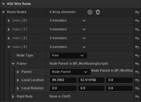
The AGX Wire Route category of a Wire’s Details panel.
Nodes can be manipulated either by selecting and dragging them in the viewport, or through direct edits of the array elements. The position of a route node is defined by its Frame. By default the local location and rotation is relative to the owning Wire Component, but this can be changed by setting the Parent property to some other Scene Component. In the screenshot above the route node at index 3 has the Component named Node Parent as its frame parent, meaning that at the start of the simulation the wire will be routed next to that Component. The frame parent is only considered during wire initialization, at runtime the wire is independent of the frame parent. To instead attach the wire to a Rigid Body use an Eye or Body Fixed node, see Route Node Types below, and set the Rigid Body property on the route node. Note that Parent and Rigid Body are separate things. Parent is for the initial routing and can be any Scene Component. Rigid Body affects the simulation at runtime and must be a Rigid Body Component. The Wire Component tries to keep its internal state up to date with changes in the Actors and Scene Components used as Parent but can sometimes become out of sync. If this happens select the affected Wire Component and click the Synchronize Parent Moved Callbacks and Mark Visuals Dirty buttons.
New nodes are created either by duplicating existing nodes in the viewport, through Alt-drag, or with the plus-button next to the Route Nodes Property in the Details panel. Existing nodes can be deleted either by selecting them in the viewport and pressing the Delete key, or using the drop-down menu next to each array element in the Details panel.
16.3.4. Selected Node
The currently selected node, if any, is shown in a separate category in the Details panel, immediately following the Route Notes array, reducing the need to search through the potentially large number of array elements to inspect or edit a particular route node.
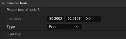
The selected node is shown in a separate Details panel category.
The following video demonstrates some of the operations outlined above.
16.3.5. Route Node Types
Each route nodes has a type, which can be one of Free, Eye, or Body Fixed, that define how it interacts with its environment. A Free node is just that, free. It can move freely through space, though it will generate contacts with geometries in the environment. An Eye node is attached to a rigid body and the wire can slide through the eye. A Body Fixed node is rigidly attached to a rigid body. A Body Fixed can only be placed at the very beginning or the very end of the wire.
The type of a particular node can be set in the Details panel, either on the element in the Route Nodes array or from the Select Node category.
Both Eye and Body Fixed nodes will move with the associated body.
Each node type has an associated color; red for Free, green for Eye, and Blue for Body Fixed. The colors are shown both in the viewport and the Selected Node category of the Details panel.
16.3.6. AGX Runtime
The AGX Runtime category of the Details panel display read-only simulation dynamic data. This includes things like the current rest length of the wire, the mass of the wire, and the tension at the begin node.
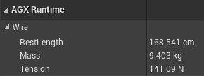
Dynamic simulation data displayed in the Details panel
16.4. Runtime Wire Creation
A Wire Component initializes itself, i.e. reads the routing nodes, on Begin Play. This means that a Wire created with the Add AGX Wire Component Blueprint Visual Script node during play will be initialized before the script has had a chance to configure it. One way around this is to create an Actor Blueprint class that creates and configures the Wire Component in its Construction Script. The Construction Script is executed before Begin Play so any alterations done to the routing nodes there will be included in the Wire initialization. The following screenshot demonstrates the idea.
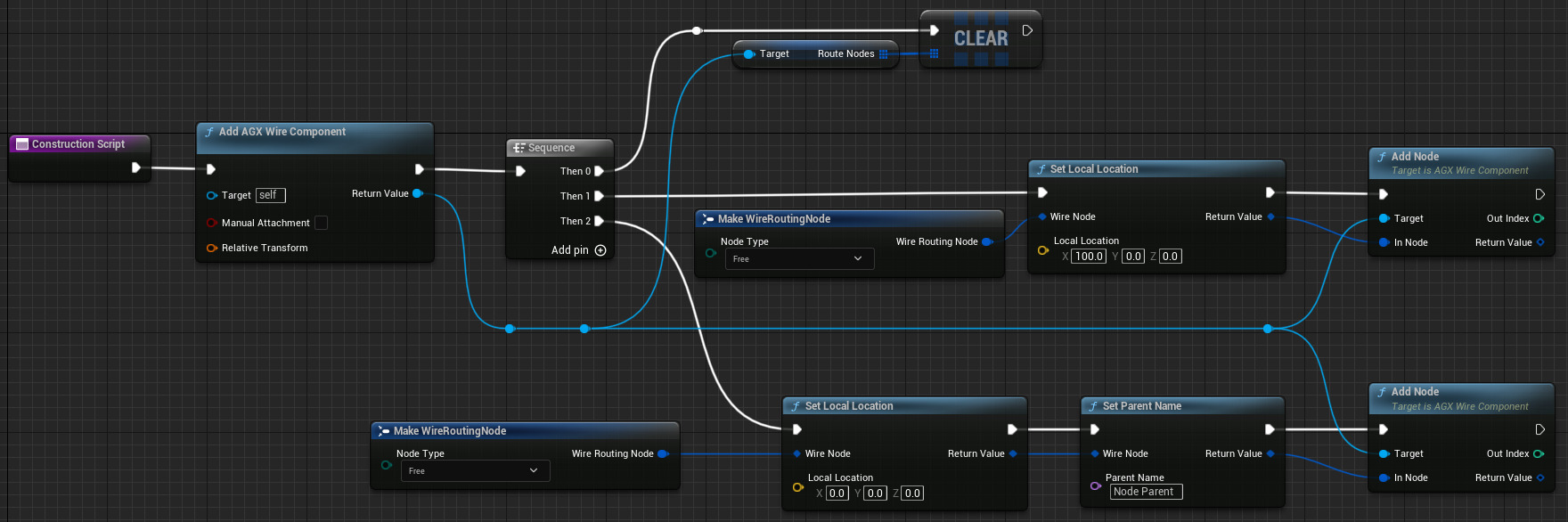
Creating and configuring a Wire Component from a Blueprint Actor Construction Script.
16.5. Wire Winch
A Wire Winch is a device that can pay out and haul in wire. Each side, begin or end, of a Wire may be connected to a Wire Winch. A Wire Winch has a motor to pay out (positive speed) or haul in (negative speed) wire, and a break to stop the wire. Both of these have a separate force range. A Wire Winch also has a Pulled In Length, with is the amount of wire that exists inside the winch. As wire is being payed out that number goes down and once it reaches zero no more wire can be payed out.
A Wire Winch can be attached to a rigid body. If a body has been selected then the position and rotation of the Wire Winch is relative to that body. Otherwise it is relative to the Component owning the Wire Winch. The Wire Winch can be positioned and rotated using the viewport visualization.
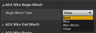
Selection drop-down for the Wire Winch owner types for the Begin Winch of a Wire.
A Wire Winch can have one of three types of owners. When owned by a Wire the Wire Winch is configurable directly from the Wire’s Details panel. A Wire Winch can also be owned by a dedicated Wire Winch Component. In that case the Wire’s Details panel contains a reference to the Wire Winch Component and any configuration of the Wire Winch properties must be done on the Wire Winch Component. The final Wire Winch owner type is Other, which means that the Wire has been assigned a Wire Winch through code, and the Wire Winch can be owned by anything. The Wire Details panel will not display anything when the owner type is set to Other.
The following video demonstrates how to use a Wire-owned Wire Winch on the begin side.
16.6. Wire Controller
The Wire Controller manages global wire settings, those which affect all wires or inter-wire interactions.
The Wire Controller is a singleton, which means that there is only one and it is always available.
It is accessed with the UAGX_WireController::Get function in C++ and the Get Wire Controller node in Blueprint Visual Script.
16.6.1. Wire-Wire Collisions
Wire-wire collisions are disabled by default but can be enabled per wire-pair.
To enable collisions for a pair of wires use the SetCollisionsEnabled function,
passing in the two wires, which can be the same Wire twice to enable self-collisions, and a Boolean specifying if collisions should be enabled or disabled.
The return value reports if the change was successful, which will only fail if None / nullptr was passed for one of the Wires, or if initialization failed for either Wire.
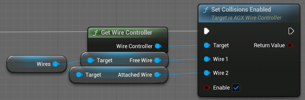
How to enable collisions between two wires.
There is a corresponding Get function to check if collisions detection is enabled for a particular pair of wires.
More details about the wire-wire collisions, in particular tips for stability, can be found in the Wire-wire interaction section of the AGX Dynamics user manual.
16.6.2. Dynamic Wire Contacts
AGX Dynamics has two contact models when a Wire is in contact with a Shape.
The default is called the kinematic contact model and is optimized for computational performance and stability under high tension.
If you need high-fidelity interactions between Wires and some particular Shape or Shapes then the dynamic contact model should be used instead.
This gives a more realistic and dynamic behavior in the contacts at the cost of computational performance and not being able to handle as high tension in the Wires.
The dynamic contact model is enabled per-Shape using SetDynamicWireContactsEnabled,
which is overloaded to take either a Shape or a Rigid Body to enable the dynamic contact model for all Shapes currently in that Rigid Body.
It is also possible to enable the dynamic contact model globally, for all Shapes, using SetDynamicWireContactsGloballyEnabled.
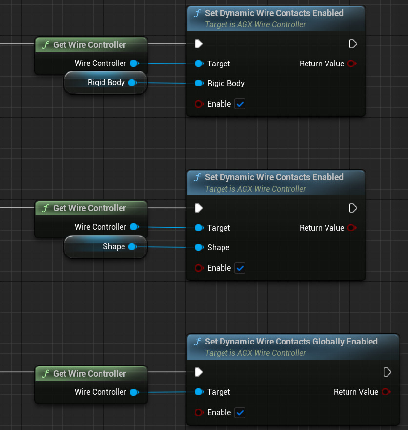
How to enable the dynamic contact model for a Shape, all Shapes in a Rigid Body, or globally for all Shapes.
More details about dynamic wire contacts can be found in the Dynamic wire contact mode section of the AGX Dynamics user manual.
16.7. Troubleshooting
If experiencing “ghosting” rendering effects for the Wire, see Rendering “Ghosting” Effects.