24. Sensors
24.1. Sensor Environment
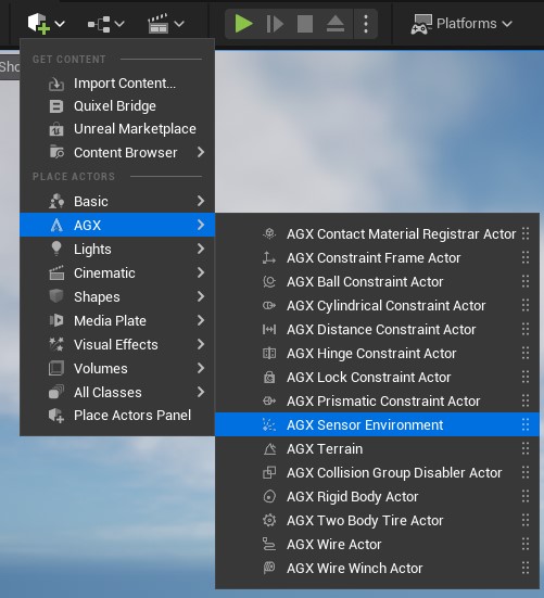
Adding a Sensor Environment Actor to the Level.
The Sensor Environment Actor is responsible for keeping track of objects that should be detectable by Sensors such as e.g. Lidar, as well as any active Lidar Sensor Component or IMU Sensor in the Level.
That means that everything that should be detectable by a Lidar Sensor Component needs to be added to the Sensor Environment.
This can be done automatically by enabling the Auto Add Objects property in the Details Panel:
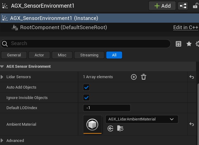
Sensor Environment Actor Details Panel.
For more details about the Auto Add Objects property, see Auto Add Objects.
Objects can only be added to a Sensor Environment during Play.
If more granular control over which objects in the Level should be added to the Sensor Environment, the Auto Add Objects property can be left unchecked, and objects can be added manually by calling any of the Add functions exposed by the Sensor Environment Actor.
To access these Add functions from a Blueprint, a Blueprint with parent class Sensor Environment Actor can be used:
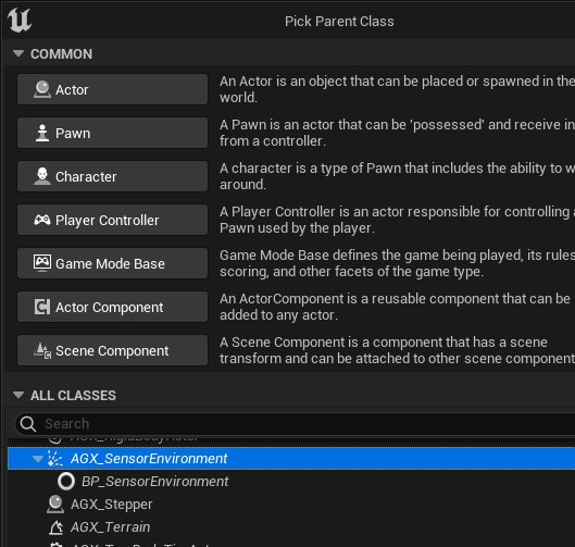
Creating a Blueprint with Sensor Environment parent.
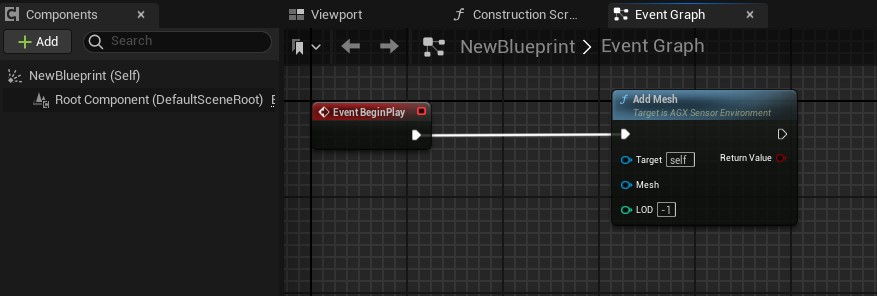
Manually calling the Add Mesh function on a Sensor Environment.
When a Static Mesh or Instanced Static Mesh is added to the Sensor Environment, the triangle data of that Mesh is read and given to the underlying AGX Dynamics agxSensor::Environment during Play.
All active Lidar Sensor Component in the Level has to be registered with the Sensor Environment. This is done by adding a reference to it from the Sensor Environment Actor Details Panel.
24.1.1. Auto Add Objects
When the Auto Add Objects property of a Sensor Environment is enabled, the Sensor Environment will automatically add objects in the Level to itself so that they can be detected by Lidars in the same Level.
To do this in a memory efficient manner, not all objects in the Level are added at once, but instead objects are dynamically added and removed depending if they are within the range of any Lidars in the Level.
More concretely, the Sensor Environment does this by automatically creating a “collision” sphere around each Lidar with radius equal to the maximum range of the Lidar.
These collision spheres follow their respective Lidar as they move about in the Level.
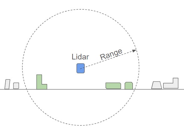
Collision sphere created by the Sensor Environment to track objects in the Level.
Each time an object overlap with a collision sphere is detected, the object is added to the Sensor Environment. Similarly, each time an objects stops being overlapped by a collision sphere, the objects is removed. To support multiple Lidars in the same Level, reference counting is used internally.
The detection of object overlaps with a collision sphere relies upon Unreal Engine’s UPrimitiveComponent overlap events. For this to trigger for a Static Mesh, two criteria must be met:
The Static Mesh Component has the
Generate Overlap Eventsproperty enabled:
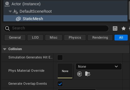
There is Simple collision data available for the Mesh asset:
The Component is Visible (relevant if using the
IgnoreInvisibleObjectsproperty of the Sensor Environment).
Note
It is NOT recommended to use the Use Complex Collision as Simple option neither for Static Mesh Assets nor in the Unreal Project settings.
This is because of an Unreal issue where end/begin overlap events are triggered each tick during overlap when using this option which may cause performance issues.
Also note that Static Meshes imported from an AGX Dynamics archive will automatically get Simple Collision from the version that Lidar was released in AGX Dynamics for Unreal. Older imported assets may need to be reimported, see Reimport Model.
AGX primitive Shape Components will generate overlap events by default, but can be disabled by setting the Additional Unreal Collision to No Collision in the AGX Shape category in the Details Panel.
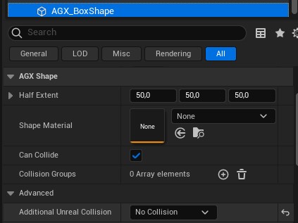
Disabling overlap events for an AGX primitive Shape Component.
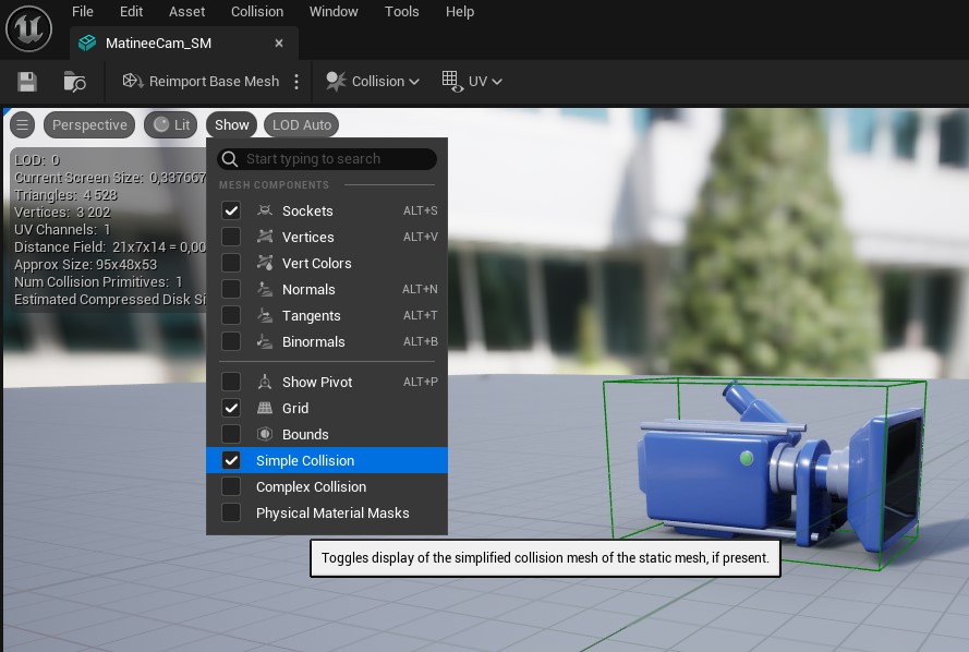
If a Mesh asset lacks Simple collision data, and is thus not added to the Sensor Environment when using the Auto Add feature, it can be added by selecting the Collision menu in the Mesh asset editor:
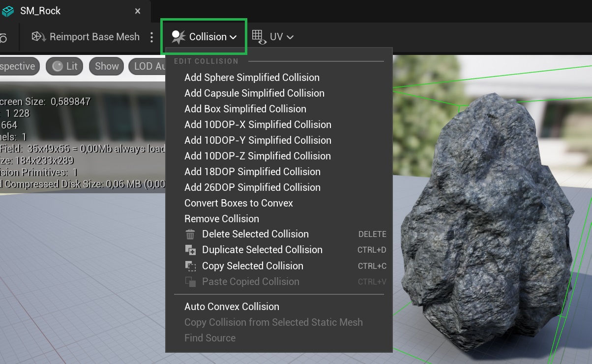
Add Simple collision data for a Mesh asset.
24.1.2. Ambient Material
It is possible to assign an Ambient Material to the Sensor Environment. This material is used to simulate atmospheric effects on the Lidar laser rays such as rain, fog, snowfall etc. Assigning an Ambient Material to the Sensor Environment is done from it’s Details Panel.
A number of pre-defined Ambient Materials come with AGX Dynamics for Unreal, see Material Library for details.
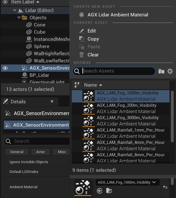
Pre-defined Lidar Ambient Materials that come with AGX Dynamics for Unreal.
It is also possible to configure a Lidar Ambient Material as specific Air, Fog, Rainfall or Snowfall using the helper buttons in the Details Panel of any Lidar Ambient Material Assets:
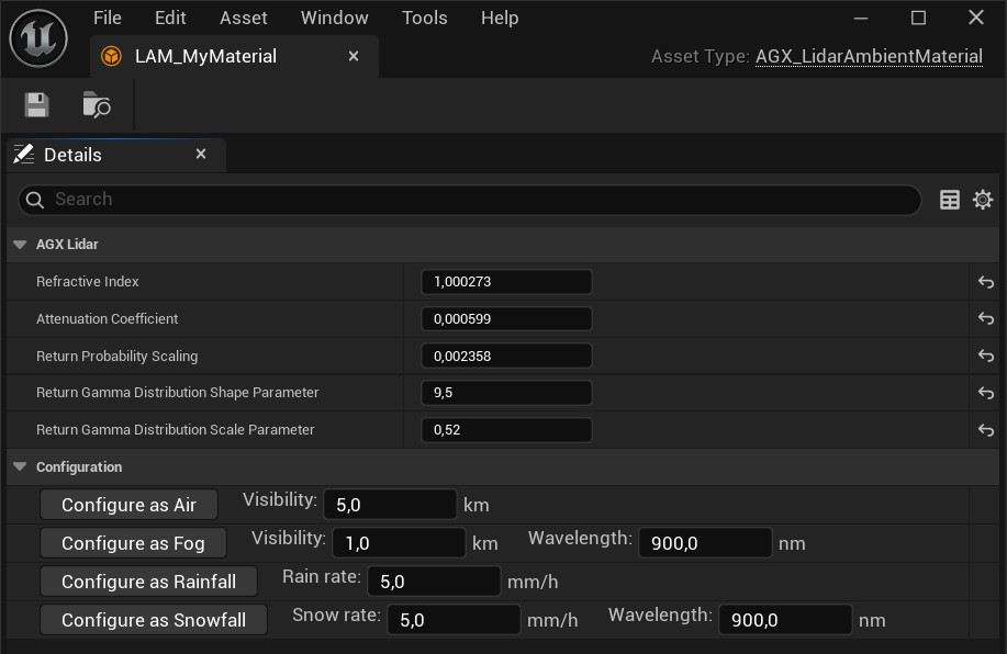
Configure a Lidar Ambient Material Asset as Air, Fog, Rainfall or Snowfall from the Details Panel.
24.1.3. Magnetic Field
A (uniform) Magnetic Field can be set on the Sensor Environment and will affect any IMU Sensor that uses a Magnetometer.
Set the Magnetic Field associated with the Sensor Environment in it’s Details Panel.
The Magnetic Field is measured in Tesla [T].
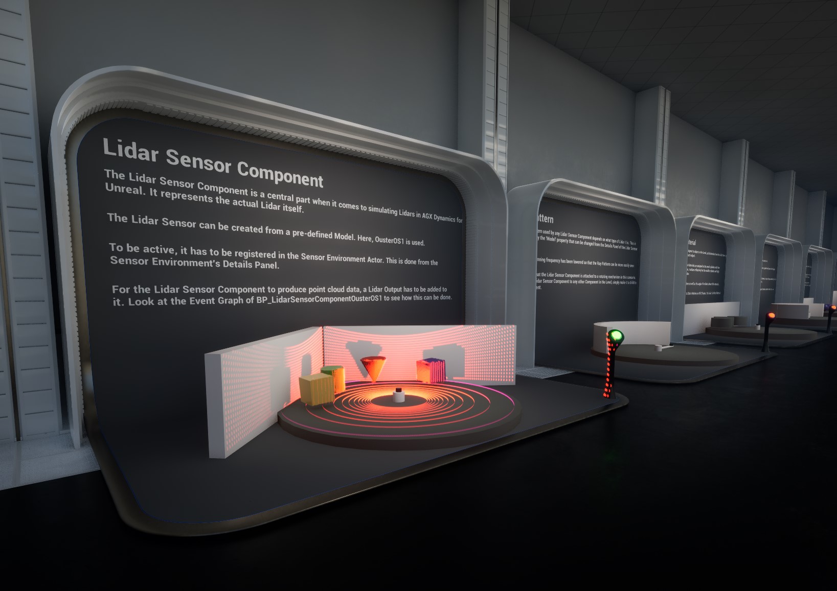
24.2. Lidar Sensor
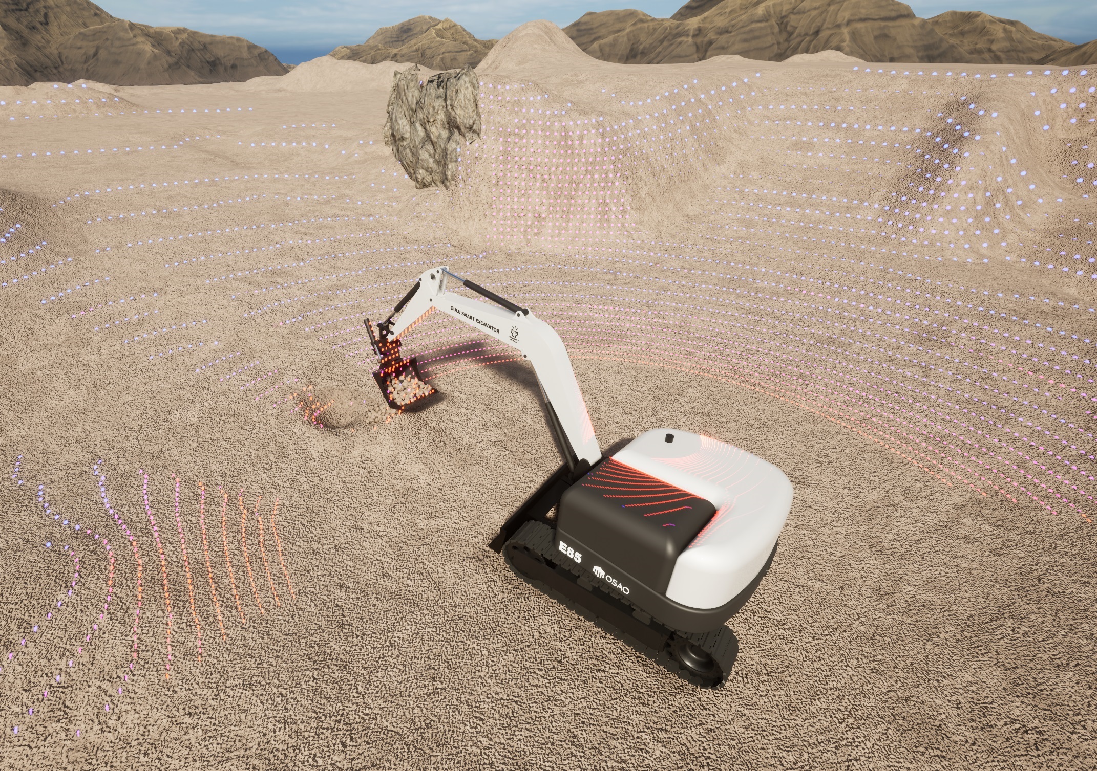
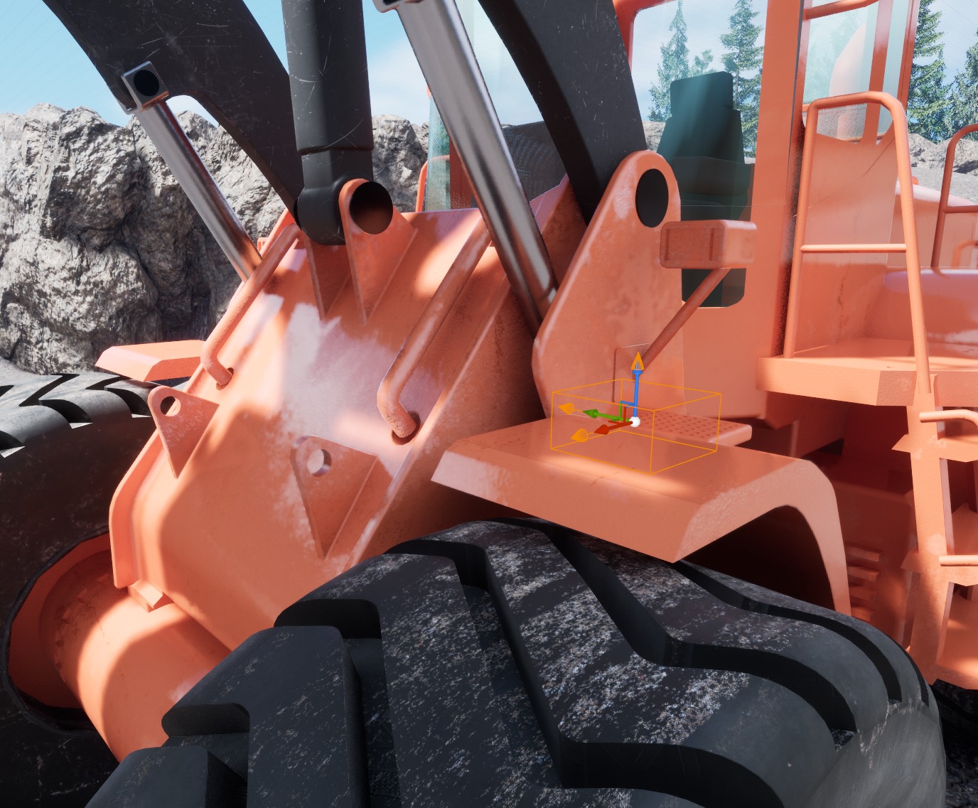
A lidar attached to an Excavator.
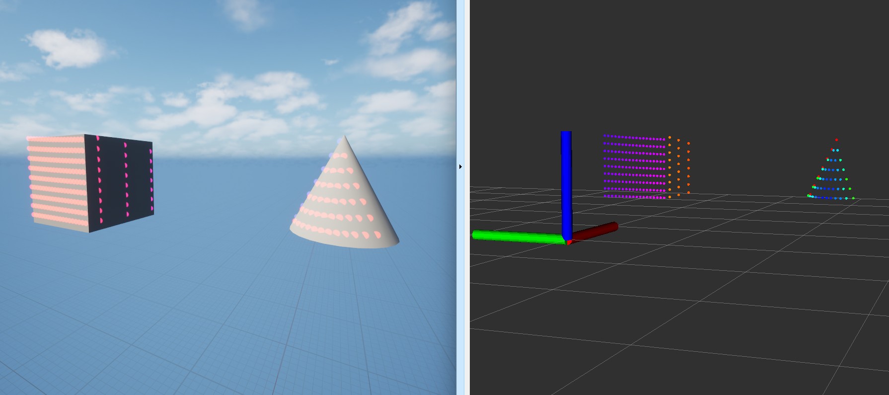
AGX Dynamics for Unreal offers the ability to simulate many types of real world Lidar sensors, as well as custom Lidar sensors. Hardware accelerated ray tracing is used to enable good performance with high output rates. Output data such as Position, Intensity, Normal vector and many others are available and can be configured by the user. Custom ray patterns are also supported.
It uses the AGX Dynamics agxSensor::Lidar, see the Lidar section of the AGX Dynamics user manual.
The three main parts that needs to be set up to simulate Lidar are: Sensor Environment, Lidar Sensor Component and Lidar Output, each described in more details in subsections below.
The main steps needed to simulate Lidar are:
Add a Sensor Environment Actor to the Level.
Add a Lidar Sensor Component to a Blueprint and configure it in the Details Panel.
Add one or more Lidar Outputs to the Lidar Sensor Component in the Event Graph of the Blueprint.
Instantiate the Blueprint in the Level and register the Lidar Sensor Component in the Sensor Environment Actors Details Panel.
These steps are explained in more detail in the subsections below.
Try out the Lidar level, included in the Tutorial Hallways Demo Project
The Lidar level of the Tutorial Hallways demo project.
24.2.1. Lidar Sensor Component
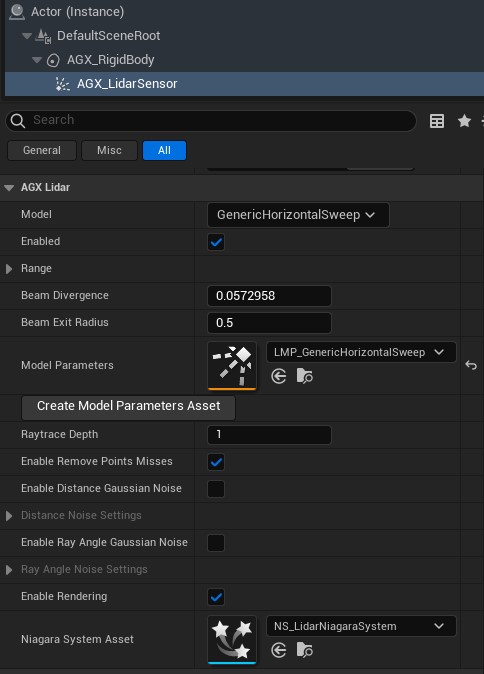
Lidar Sensor Component Details Panel.
The Lidar Sensor Component is a central part of setting up a Lidar Simulation.
It can be created from a number of pre-defined models in its Details Panel, by selecting a Model.
Using a custom ray pattern is also supported, see Custom Ray Pattern for details.
A Lidar Sensor must be added to a Sensor Environment in order to be active, see Sensor Environment.
For a Lidar to produce some output data, a Lidar Output must be added to it, see Lidar Output for details.
To attach a Lidar to any other Component moving in the Level, simply make it a child to that Component.
24.2.1.1. Custom Ray Pattern
It is possible to define and use a custom ray pattern with the Lidar Sensor Component. The responsibility of anyone defining a custom ray pattern is to set the rays as an array of transforms once. Then, each time the Simulation steps, an interval within the set rays array must be returned so that AGX knows which rays to use for that step.
To use a custom ray pattern, select the CustomRayPattern Model in the Lidar’s Details Panel.
Assign a Model Parameters Asset of the appropriate type.
Then, assign a function to the On Fetch Ray Transforms delegate.
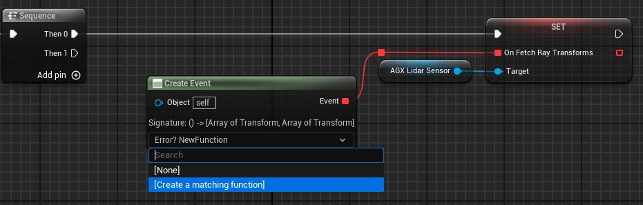
Create a function and assign it to the On Fetch Ray Transforms delegate.
Do the same for the On Fetch Next Pattern Interval delegate.
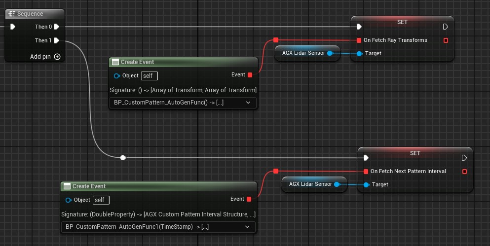
Create a function and assign it to the On Fetch Next Pattern Interval delegate.
In the function assigned to the On Fetch Ray Transforms delegate, the rays, represented as an array of transforms, must be set.
This function is called once at the start of the Simulation.
Each transform in the array represents a single ray, and will shoot out in the z-direction.
The transforms are expressed in local coordinates to the Lidar frame.
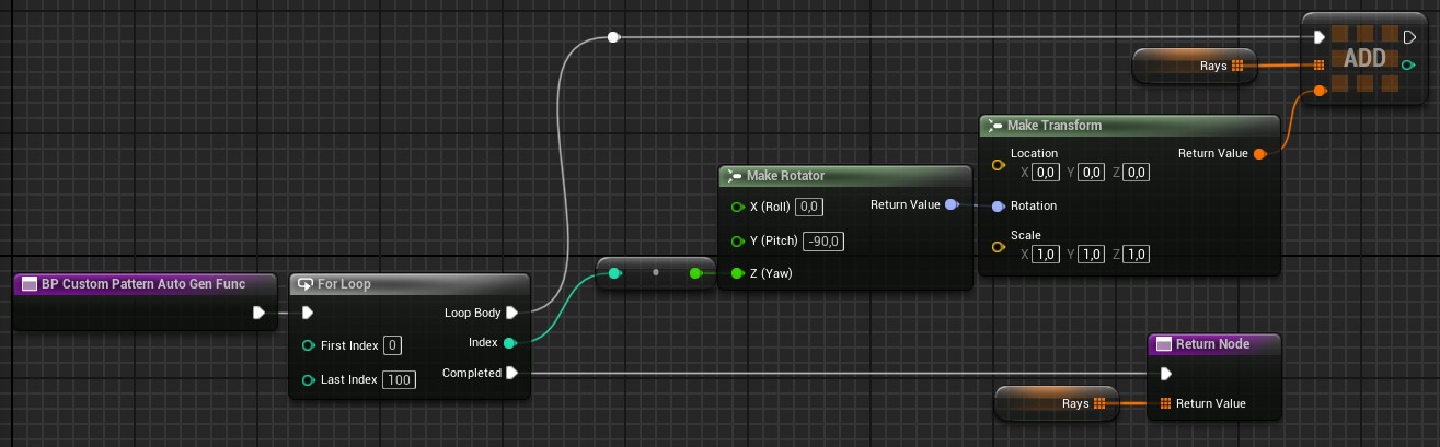
An example function assigned to the On Fetch Ray Transforms delegate.
Each time the Simulation ticks, the function assigned to the On Fetch Next Pattern Interval delegate will be called.
Here, an interval within the rays transforms array must be returned.
An example function assigned to the On Fetch Next Pattern Interval delegate.
24.2.2. Lidar Surface Material
A Lidar Surface Material determines how Lidar laser rays interact with surfaces that they hit. This is important for example when the intensity of the returning Lidar laser beam is calculated.
The Lidar Surface Material can be assigned to any Component or Actor supported by the Sensor Environment. These include AGX primitive Shapes, Static Mesh Components (including Instanced and Hierarchical), Terrains etc.
To assign a Lidar Surface Material to a Component, the Lidar Surface Material Component can be used.
Lidar Surface Material Component used for assigning Lidar Surface Materials to Components in the Level.
By setting the Selection property, the Lidar Surface Material Component can assign a Lidar Surface material to either its parent, siblings or children in the Component attachment hierarchy.
For example, by making a Lidar Surface Material Component the parent of several Static Mesh Components, and then setting the Selection property to Children, all Static Mesh Components attached to the Lidar Surface Material Component will be assigned the selected Lidar Surface Material.
The assignment is done in Begin Play, and works by it adding a UAGX_SurfaceMaterialAssetUserData instance containing a reference to the selected Lidar Surface Material to the relevant Component(s) Asset User Data. Then, when a Component is added to the Sensor Environment, the Asset User Data is queried to find the Lidar Surface Material, and the information is handed to AGX Dynamics. As an advanced usage, it is therefore possible to manually add UAGX_SurfaceMaterialAssetUserData to any Component supported by the Sensor Environment instead of using the Lidar Surface Material Component.
It is possible to set a default Lidar Surface Material that will be used on all objects added to the Sensor Environment that has no Lidar Surface Material assigned.
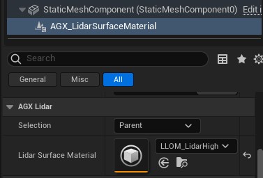
To set this, select Edit > Project Settings... > Plugins > AGX Dynamics and in the Lidar category set Default Lidar Surface Material.
Default Lidar Surface Material in the AGX Dynamics for Unreal plugin settings.
If no default Lidar Surface Material has been set in the Project Settings, the AGX Dynamics default Lidar Surface Material is used.
The Terrain is an Actor and therefore the Asset User Data approach cannot be used for it.
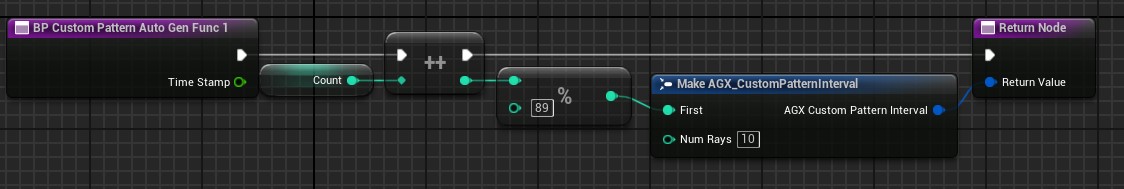
Instead, a Lidar Surface Material can be assigned directly to the Terrain Actor from the Details Panel under the AGX Lidar category.
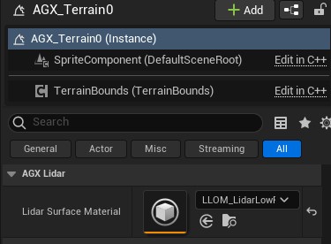
Lidar Surface Material assigned to a Terrain in its Details Panel.
While live updating the Lidar Surface Material properties during Play is supported, it is currently not supported to assign new Lidar Surface Materials to objects in the Level during play. See Limitations.
24.2.3. Lidar Output
A Lidar Output determines what data is produced by the Lidar Sensor Component.
To add a Lidar Output to an instance of a Lidar, the AddTo function is called on it, which can be done either from Blueprint or C++.
The built in Lidar Output types are:
AGX Lidar Output Position - produces position (x, y, z) data for each point.
AGX Lidar Output Position Intensity - produces position (x, y, z) and intensity data for each point.
If working with Blueprint, typically a Lidar Output is created as a variable (see figure below), and then the AddTo function is called to add it to a Lidar.
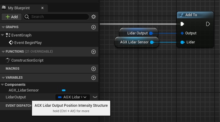
Creating a Lidar Output variable and calling Add To function on it.
A Lidar Output should only ever be added to a single instance of a Lidar.
24.2.3.1. Getting Output Data
To access the Lidar Output data, the GetData function should be called.
This should be done during Simulation Post Step Forward (see Events and Delegates for details):
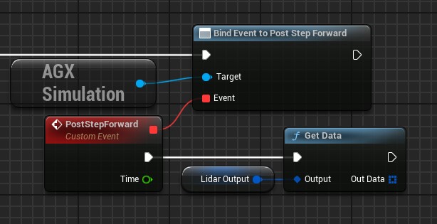
Getting data from a Lidar Output.
The Lidar Output data can be used directly or converted to a ROS2 message sensor_msgs::PointCloud2 which can then be sent via ROS2:
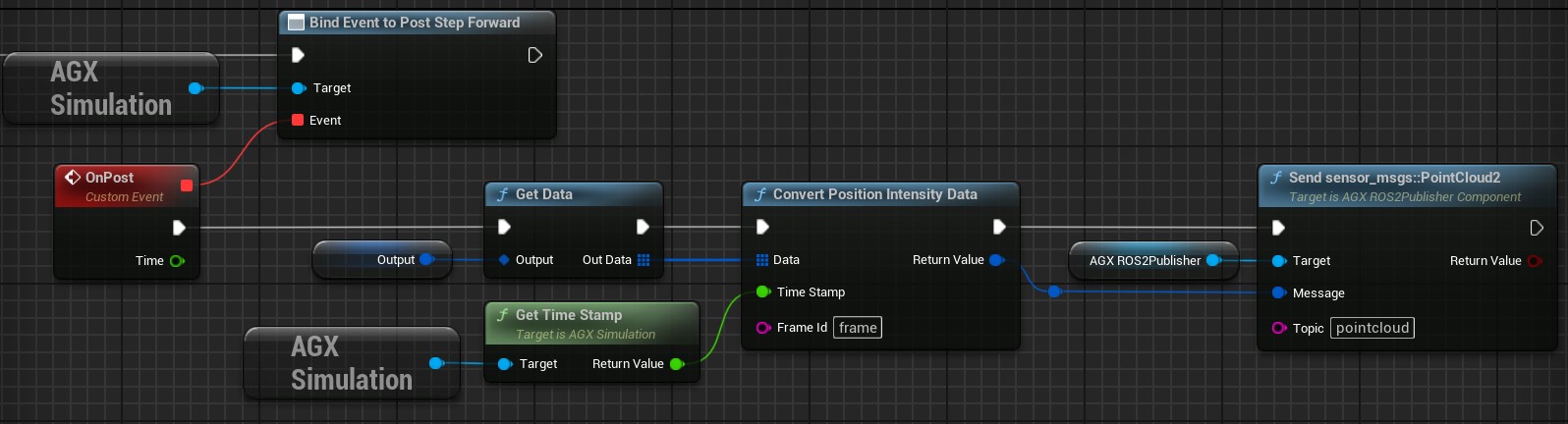
Converting and sending output data as a ROS2 sensor_msgs::PointCloud2 message.
The pointcloud data can then be received in RViz:
Receiving point cloud data in RViz.
To succesfully receive the point cloud data sent from AGX Dynamics for Unreal, ensure the frame name and topic matches (see image below):
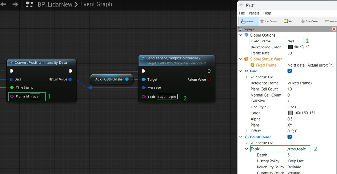
RViz settings.
For more details on ROS2 publishers and subscribers in AGX Dynamics for Unreal see ROS2.
24.2.3.2. Rendering of Output Data
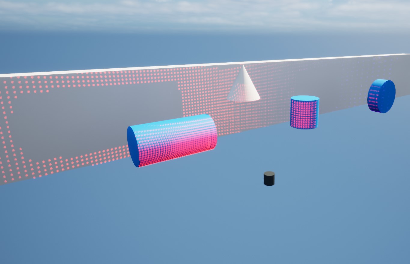
Lidar output data rendered in the Level.
To render the Lidar Output data, the Render function may be called.
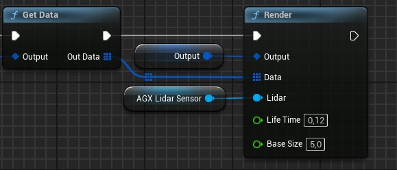
Rendering output data from a Lidar Output.
This rendering works by the Lidar Output writing data to a Niagara System owned by the Lidar Sensor Component.
The Enable Rendering property must also be enabled on the Lidar Sensor Component for the rendering to be available.
Data for each point is written to the Niagara particle system in buffers using the Niagara Data Interface from C++. The buffers written are:
Positions - array containing x, y and z position of each point in global coordinates.
Colors - array containing Linear Color for each point, can be used to visualize intensity for example.
User.NumPoints - integer value of how many points to spawn.
User.Lifetime - floating point value of the lifetime of the rendered points.
User.ZeroDistanceSize - floating point value of the smallest size of a rendered point.
Note that rendering of the Lidar Output data comes with a performance cost. Also note that rendering of multiple Lidar Outputs added to the same Lidar Sensor Component is not supported.
24.2.3.3. Output Data Frequency
By defailt, the Lidar produces Output data each AGX Step Forward.
The Output frequency, i.e. how often the Lidar should produce Output data, can be changed by setting the Step Stride property in the AGX Sensor category of the Lidar Sensor Component Details Panel.
Step Stride determines how many times AGX Step Forward is executed before the next Output is produced.
Default value is 1, meaning that Output data is produced each AGX Step Forward.
24.2.4. GPU Selection for Multi-GPU Systems
If the computer used has multiple RTX enabled GPU devices available, it is possible to select which of them the Lidar Raytrcing should be executed on.
This is done from Edit > Project Settings... > Plugins > AGX Dynamics.
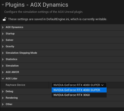
Selecting GPU device for Lidar Raytracing.
24.2.5. Troubleshooting
24.2.5.1. No output data is created
Make sure the Lidar Output has been properly set up, see Lidar Output.
Check the Output Log for any Warnings or Errors.
Make sure your license has the
AGX-Sensormodule. Modules are listed in theAGX > License > Activate service license...window.Check if the same issue also occurs in one of the Demo Projects that uses Lidar. For example the
LidarLevel of theTutorialHallwaysdemo.
24.2.5.2. Framerate Drops Significantly
From within the Unreal Editor, run the command stat unit to get information about GPU and CPU usage.
If the GPU usage too high when using Lidar in the Level, you may try the following:
Improve the overall performance of running the Level.
Use a more powerful Graphical Processing Unit (GPU).
Run the Lidar Raytracing on a different GPU, see GPU Selection for Multi-GPU Systems.
24.2.5.3. Meshes not added to Sensor Environment using Auto Add
Go through the requirements listed in Auto Add Objects. If Simple collision data is lacking from the Mesh asset, it can be created manually in the Mesh asset editor, see Auto Add Objects for details.
24.2.6. Limitations
Lidar Raytracing is only supported on computers with at least one RTX enabled Graphical Processing Unit (GPU). Assigning Lidar Surface Materials to objects during runtime is currently not supported. Import of Lidar or Sensor Environment from an AGX Dynamics archive is currently not supported. Rendering of multiple Lidar Outputs added to the same Lidar Sensor Component is not supported.
24.3. IMU Sensor
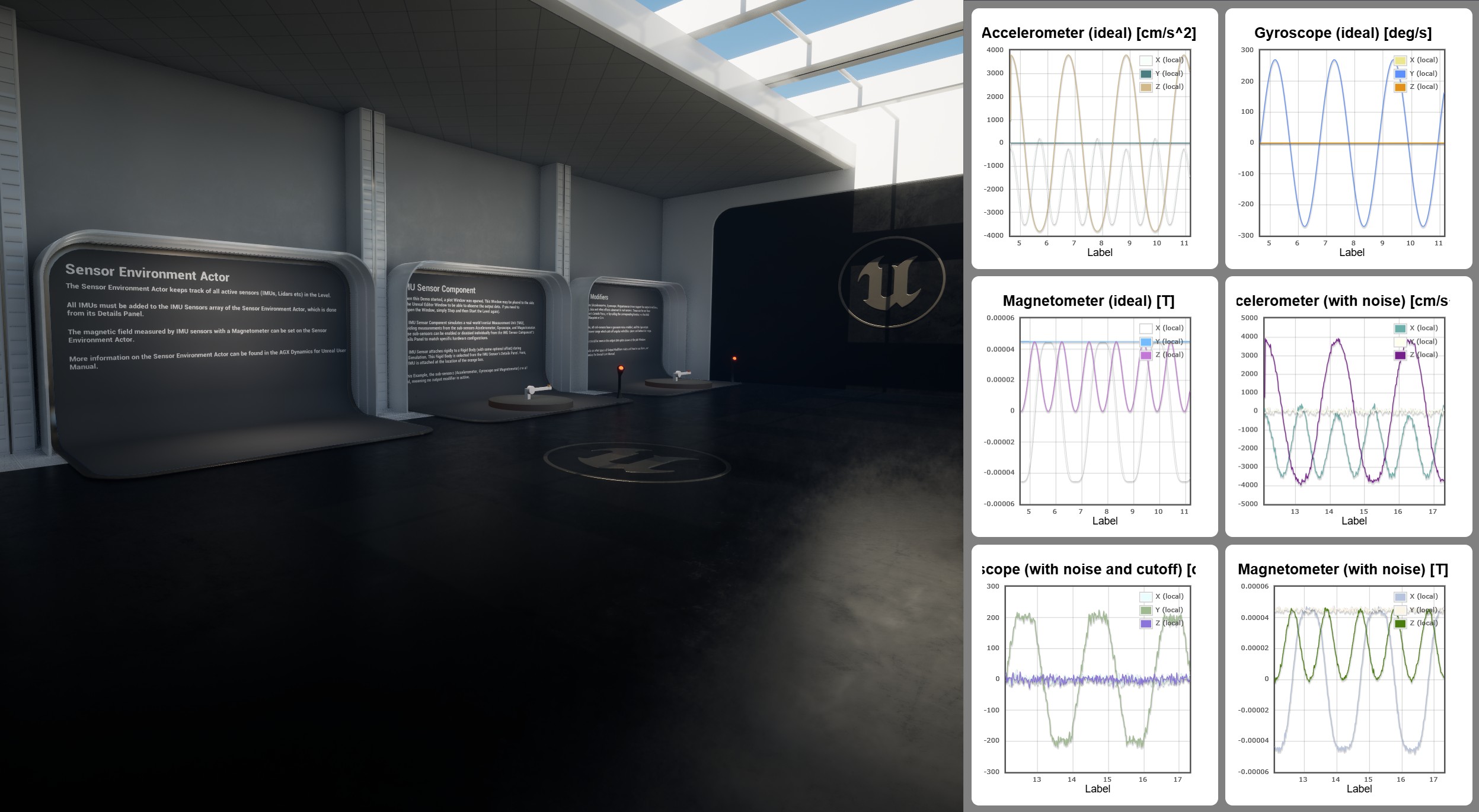
An IMU Sensor attached to a Wheel Loader.
The IMU Sensor Component simulates a real-world Inertial Measurement Unit (IMU), providing measurements from the sub-sensors Accelerometer, Gyroscope, and Magnetometer. These sub-sensors can be enabled or disabled individually from the IMU Sensor Component’s Details Panel to match specific hardware configurations. It attaches to a Rigid Body (with some optional offset) during the Simulation, see Attachment for details.
Noise and other hardware effects can be configurable to produce realistic output data, see Output Modifiers.
It uses the AGX Dynamics agxSensor::IMU, see the IMU section of the AGX Dynamics user manual.
The main steps needed to simulate an IMU Sensor are:
Add a Sensor Environment Actor to the Level.
Add an IMU Sensor Component to a Blueprint and configure it in the Details Panel.
Access IMU data (Accelerometer, Gyroscope, Magnetometer) in Blueprint or C++.
Instantiate the Blueprint in the Level and register the IMU Sensor Component in the Sensor Environment Actor’s Details Panel.
To get output data from the IMU Sensor, see Getting Output Data.
The IMU Sensor output data can easily be converted to a sensor_msgs::Imu ROS2 message that can be sent via ROS2, see Getting Output Data for details.
Try out the IMU level, included in the Tutorial Hallways Demo Project
The IMU level of the Tutorial Hallways demo project.
More details on the features and how to use the IMU Sensor can be found below.
24.3.1. Attachment
The IMU Sensor Component needs a Rigid Body to attach to during the Simulation. It can be selected from the IMU Sensor Component’s Details Panel:
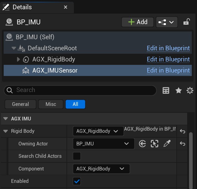
The Rigid Body this IMU Sensor will be attached to during Simulation.
Note that the initial relative transform between the IMU Sensor and the Rigid Body will be preserved during the simulation.
24.3.2. Getting Output Data
The IMU Sensor Component provides API functions for retrieving measurements in local coordinates (relative to the IMU frame) or world coordinates.
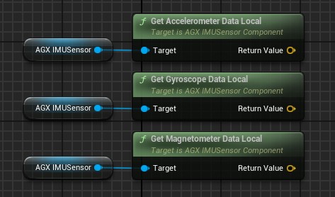
Getting data from the IMU Sensor in Blueprint.
These functions are also avaiable in C++. If a function is called for a sub-sensor that is not enabled, the returned data will not be valid.
The units for the Accelerometer data is [cm/s^2]. The units for the Gyroscope data is [deg/s]. The units for the Magnetometer data is [T].
See Physical Quantities and Units for details.
The IMU Output data can be used directly or converted to a ROS2 message sensor_msgs::Imu which can then be sent via ROS2:

Converting and sending output data as a ROS2 sensor_msgs::Imu message.
24.3.2.1. Output Data Frequency
By defailt, the IMU Sensor produces Output data each AGX Step Forward.
The Output frequency, i.e. how often the IMU Sensor should produce Output data can be changed by setting the Step Stride property in the AGX Sensor category of the IMU Sensor Component Details Panel.
Step Stride determines how many times AGX Step Forward is executed before the next Output is produced.
Default value is 1, meaning that Output data is produced each AGX Step Forward.
24.3.3. Output Modifiers
All sub-sensors (Accelerometer, Gyroscope, Magnetometer) have support for output modifiers, such as noise, bias and other effects observed in real sensors. These can be set from the IMU Sensor’s Details Panel, or by calling the corresponding function on the IMU Sensor from Blueprint or C++.

IMU Sensor’s Details Panel where output modifiers can be configured.
Below, the output modifiers available for each sub-sensor is listed.
24.3.3.1. Accelerometer
The Accelerometer supports the following output modifiers (shown in the AGX Accelerometer section of the IMU Sensor Component’s Details Panel):
Range — Detectable acceleration interval [cm/s²]. Output is clamped to this range.
Cross Axis Sensitivity — Cross-axis coupling factor; how much acceleration on one axis bleeds into another.
Zero G Bias — Constant measurement bias per axis at zero external acceleration [cm/s²]. Bias is added at any measured acceleration.
Noise RMS — Gaussian noise RMS per axis [cm/s²].
Spectral Noise Density — Frequency-dependent Gaussian noise density per axis [cm/s²/Hz].
24.3.3.2. Gyroscope
The Gyroscope supports the following output modifiers (shown in the AGX Gyroscope section of the IMU Sensor Component’s Details Panel):
Range — Detectable angular-rate interval [deg/s]. Output is clamped to this range.
Cross Axis Sensitivity — Cross-axis coupling factor; how much rate about one axis bleeds into another.
Zero Rate Bias — Constant measurement bias per axis at zero angular rate [deg/s]. Bias is added at any measured rate.
Noise RMS — Gaussian noise RMS per axis [deg/s].
Spectral Noise Density — Frequency-dependent Gaussian noise density per axis [deg/s/Hz].
Linear Acceleration Effects — Per-axis multiplier letting linear accelerations perturb the gyroscope output.
24.3.3.3. Magnetometer
The Magnetometer supports the following output modifiers (shown in the AGX Magnetometer section of the Details Panel):
Range — Detectable magnetic-flux interval [T]. Output is clamped to this range.
Cross Axis Sensitivity — Cross-axis coupling factor; how much a magnetic field on one axis bleeds into another.
Zero Flux Bias — Constant measurement bias per axis at zero magnetic flux [T]. Bias is added at any measured field strength.
Noise RMS — Gaussian noise RMS per axis [T].
Spectral Noise Density — Frequency-dependent Gaussian noise density per axis [T/Hz].
24.3.4. Limitations
Currently, only a uniform magnetic field can be set in the Sensor Environment while in AGX Dynamics custom (user defined) magnetic fields can be created.
Sub-sensor Range is applied equally to all axes, while in AGX Dynamics separate values can be applied to individual axes.
24.4. Camera Sensor
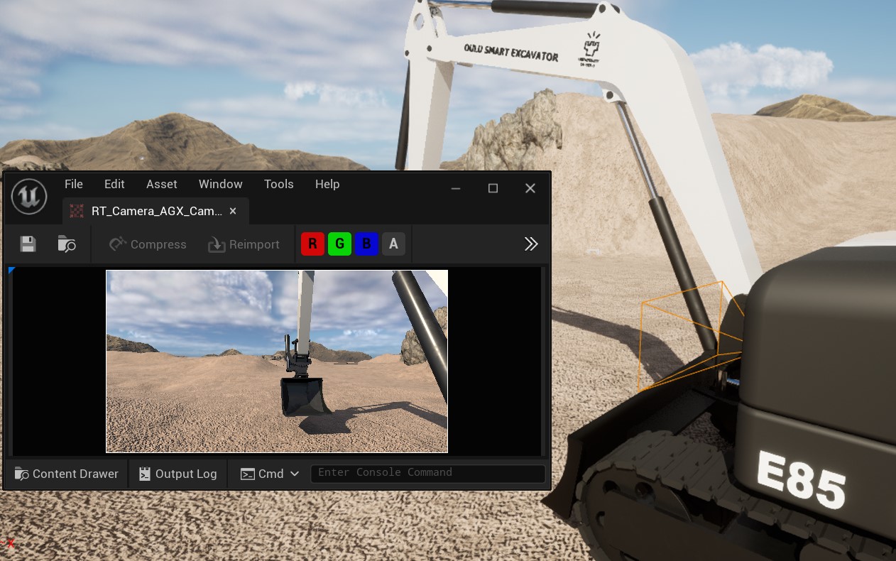
Camera Sensor on an excavator.
AGX Dynamics for Unreal provides two Camera Sensor Components, an 8-bit and a 16-bit variant, that can be used to capture the scene from that camera’s point of view. It also provides convenience functions for getting the image data either as an array of pixels (RGB) or as a ROS2 sensor_msgs::Image message. See Getting Image Data for more details. The image data is encoded in linear color space.
A field of view (FOV) and Resolution can be specified from the Details Panel:
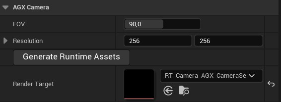
Specifying FOV and Resolution from the Details Panel.
The Camera Sensor Component renders the image information to a Render Target which must be assigned to the Component.
To make this simple, a button labeled Generate Runtime Assets is available in the Details Panel as can be seen in the image above.
It will generate a Render Target with the appropriate settings according to the specified Resolution.
This also means that if this parameter is changed, the Generate Runtime Assets procedure must be done again.
If an old Render Target is currently assigned when the Generate Runtime Assets procedure is performed, it will be updated and no new Render Target will be created.
Changing the FOV can be done during Play either from the Details Panel or by calling the function SetFOV.
To attach the Camera Sensor to a simulated machine, make it a child to the Scene Component it should follow.
24.4.1. Getting Image Data
Note
Getting the image as an array of pixels is only available in C++ and not available in Blueprint when using the CameraSensor16BitComponent due to the underlying datatype not beeing supported in Blueprint. Only getting the image as a ROS2 message is supported in Blueprint when using the CameraSensor16BitComponent.
Getting image data from the Camera Sensor Component can be done in two main ways; synchronously or asynchronously. The synchronous functions are GetImagePixels and GetImageROS2 which will return the captured image either as an array of pixels (RGB) or as a ROS2 sensor_msgs::Image message. These functions does some synchronization between the game thread and the render thread in order to return the image to the caller and can therefore be very slow.
The recommended approach is using the asynchronous versions of these, namely GetImagePixelsAsync and GetImageROS2Async. These will return immediately and whenever the image is ready an Event, or delegate, will be triggered and the image is passed to anyone listening to the Event. The workflow then is to bind to the Event, for example in BeginPlay, and then during runtime call the async function whenever a new image should be captured.
In the examples below, both getting the image as pixels as well as a sensor_msgs::Image ROS2 message are shown. In the latter example, the image is also sent via ROS2 using a ROS2 Publisher. See ROS2 for more details.
When using the 16-bit variant of the Camera Sensor, i.e. the CameraSensor16BitComponent, each pixel channel (RGB) is encoded as two consecutive 8-bit values, i.e. 48 bits per pixel in little endian format.
Getting image as an array of pixels.
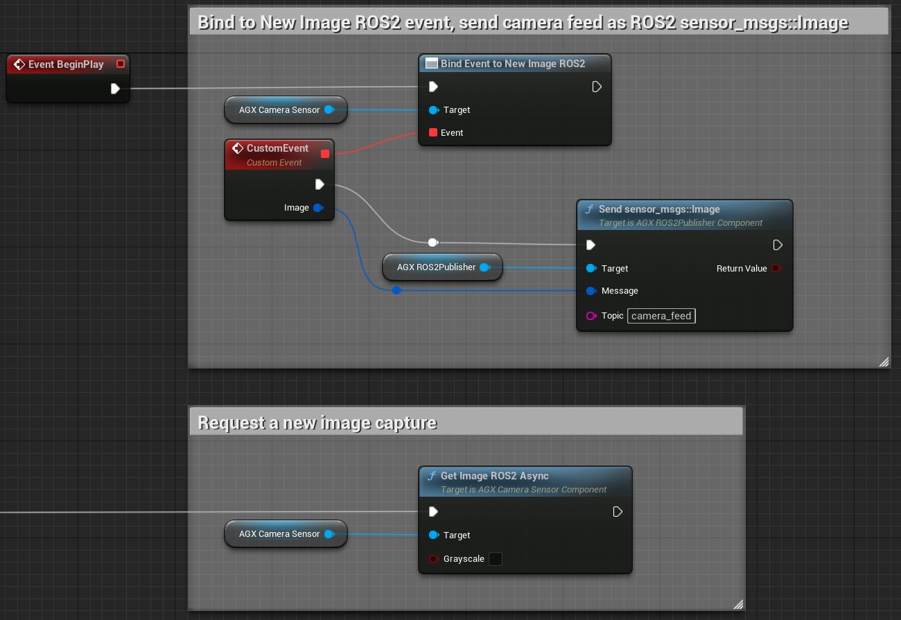
Getting image as a ROS2 sensor_msgs::Image message, and sending it via ROS2.
To do the same thing in C++, simply bind do the delegate:
CameraSensor->NewImagePixels.AddDynamic(this, &UMyClass::MyFunction);
Here, MyFunction must be a UFUNCTION taking a single const TArray<FColor>& parameter.
24.4.2. Limitations
Getting the image as an array of pixels is only available in C++ and not available in Blueprint when using the CameraSensor16BitComponent due to the underlying datatype not beeing supported in Blueprint. Only getting the image as a ROS2 message is supported in Blueprint when using the CameraSensor16BitComponent.
24.5. Lidar Sensor Line Trace
Note
This is an experimental feature meaning it may be changed in the future with no guaranteed backwards compatibility. It is recommended to use the Lidar Sensor whenever possible since that is the prioritized and main way of simulating Lidar sensors in AGX Dynamics for Unreal.
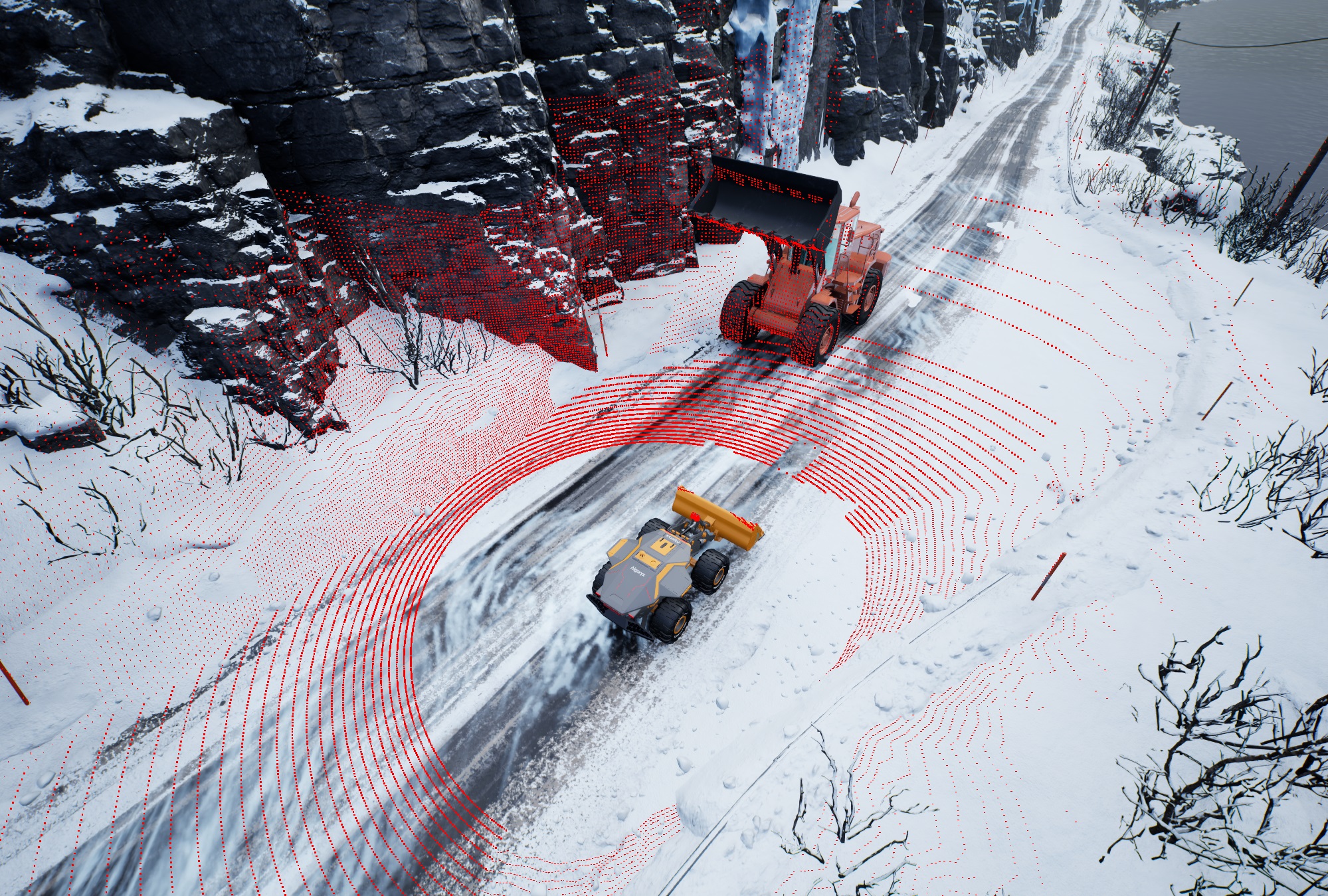
Lidar scanner attached to a wheel loader.
The Lidar Sensor Line Trace Component makes it possible to generate point cloud data in real-time.
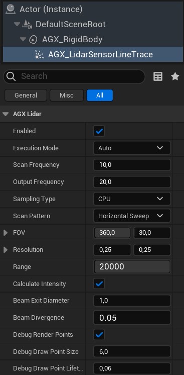
Lidar Sensor’s details panel.
The Lidar Sensor can be run in one of two Execution Modes: Auto or Manual.
In mode Auto, the Lidar Sensor will perform partial scans in each Simulation tick in a pace determined by the selected Scan Frequency.
The Scan Frequency determines how often a complete scan cycle is scanned, i.e. how often the entire Scan Pattern is covered.
In mode Manual, the Lidar Sensor does nothing unless the RequestManualScan function is called, see image below.
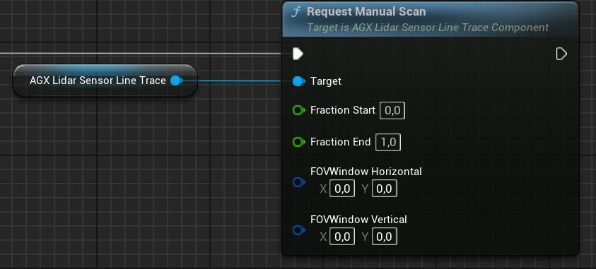
Manual scan request in Blueprint.
Here, Fraction Start and Fraction End determine at what fraction of the total scan pattern the scan should start and end respectively.
FOVWindow Horizontal and FOVWindow Vertical can be used to mask a part of the scan pattern so that any point outside this Field of View (FOV) Window is disregarded.
The Output Frequency determines how often the Lidar Sensor outputs point cloud data, see Getting Point Cloud Data for more details.
This is only used with Execution Mode Auto.
The Scan Pattern determines what points are scanned within the selected Field of View (FOV) and in what order.
For example, with the Horizontal Sweep Scan Pattern, all points along the first vertical line are scanned in succession before moving to the next vertical line.
FOV determines the Field of View of the Lidar Sensor, in degrees, along the vertical and horizontal directions respectively. The Resolution determines the minimum angular distance between two neighbouring laser rays in degrees.
The Range determines the maximum detection distance for the Lidar Sensor in centimeters. Any object further away than this distance will not be detected by the Lidar Sensor.
The Calculate Intensity option determines whether an intensity value for each Laser ray should be approximated or not. If not, the corresponding intensity value for all rays will be set to zero. To calculate the intensity, the angle of incident, material roughness parameter of the object being hit, as well as the distance is taken into account. The intensity dropoff over distance is a function of the Beam Exit Diameter and Beam Divergence that can be set for each Lidar Sensor instance.
To make a primitive AGX Shape not detectable by the Lidar Sensor, select an Additional Unreal Collision setting for that Shape that does not include query.
See Additional Unreal Collisions for more details.
To attach the Lidar Sensor to a simulated machine, make it a child to the Scene Component it should follow.
24.5.1. Getting Point Cloud Data
The way the Lidar Sensor outputs its point cloud data is via the delegate Point Cloud Data Output.
This is used in both Execution Mode Auto and Manual.
To access the point cloud data output, the user must bind to this delegate.
An example of this in Blueprint is shown below:
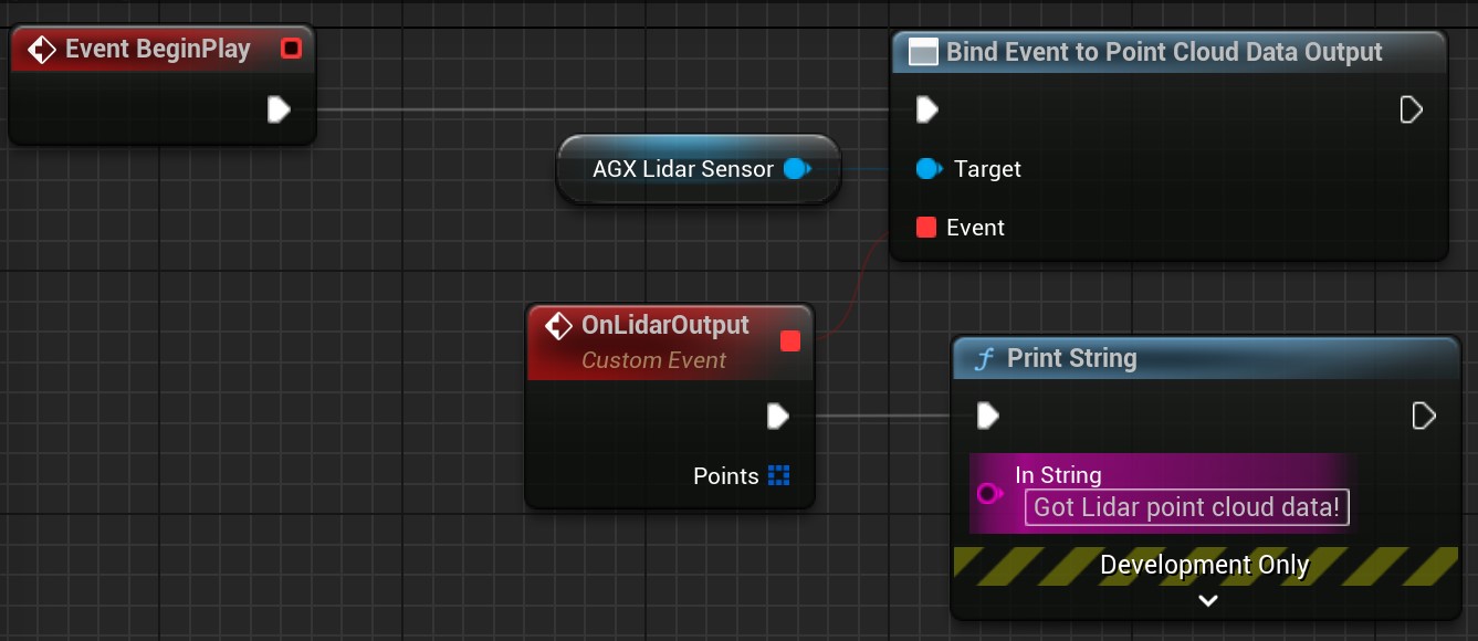
Accessing point cloud data in Blueprint.
To do the same thing in C++, simply bind do the delegate:
LidarSensor->PointCloudDataOutput.AddDynamic(this, &UMyClass::MyFunction);
Here, MyFunction must be a UFUNCTION taking a single const TArray<FAGX_LidarScanPoint>& parameter.
Note that in Execution Mode Auto, it is the Output Frequency property of the Lidar Sensor that determines how often this delegate is executed.
In Execution Mode Manual, this delegate is always called once upon calling the RequestManualScan function, as long as valid input parameters are given.
The point cloud data returned by the Point Cloud Data Output delegate is such that any laser ray miss is represented by a FAGX_LidarScanPoint with the IsValid property set to false.
24.5.1.1. ROS2 sensor_msgs::PointCloud2
A convenience function Convert XYZ is available that takes as input an array of FAGX_LidarScanPoint and converts it to a ROS2 message sensor_msgs::PointCloud2. This can then be send via ROS2 using a ROS2 publisher, see ROS2 for more details about ROS2 in AGX Dynamics for Unreal.
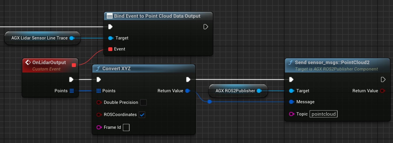
Converting point cloud data to a ROS2 message and sending it via ROS2.
An alternative version to the Convert XYZ is the convenience function Convert Angles TOF, available from Blueprint and C++, which represents each point as two angles and time-of-flight.
24.5.2. Limitations
With the current implementation, Terrain height changes as well as Terrain particles are not detected by the Lidar Sensor Component. Providing this functionality is currently in the process of being developed.