2. Editor interface
All AGX Dynamics for Unity scripts are using a custom editor that renders the Inspector GUI. The custom editor supports “editing/serialization” of objects exposed as C# properties. This feature is important to properly synchronize data or states changed during runtime, when the AGX Dynamics native instances has been created, since it’s not reasonable to synchronize all data all the time.
2.1. Main and context menus
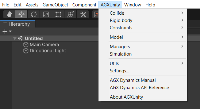
2.1.1. Main menu
Create new objects and managers and access utilities, settings and documentation.
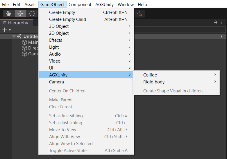
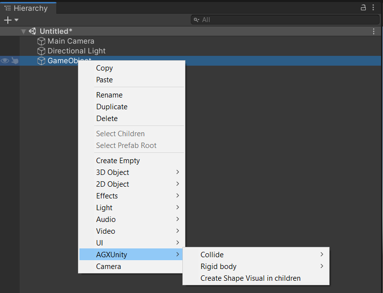
2.1.2. GameObject main and Hierarchy context menus
Inside the create section of GameObject main and Hierarchy context menu. When an object is created using the Hierarchy context menu the selected object will become parent of the new object. Main menu GameObject objects are create without parents regardless of current selection.
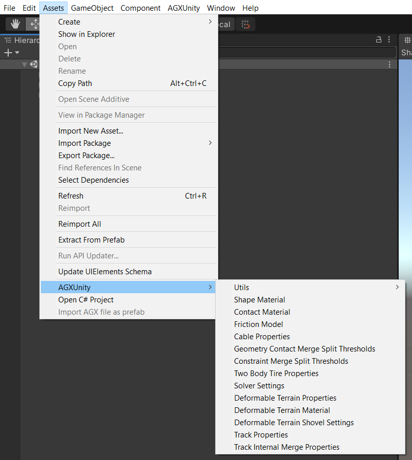
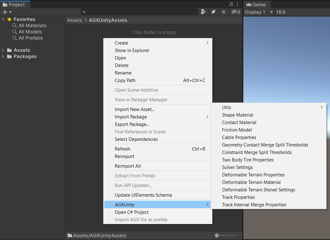
2.1.3. Assets main and context menus
Create AGX Dynamics for Unity specific assets, such as shape and contact materials, friction models, model specific properties and settings. Assets created from the main menu will be created in the current open project folder.
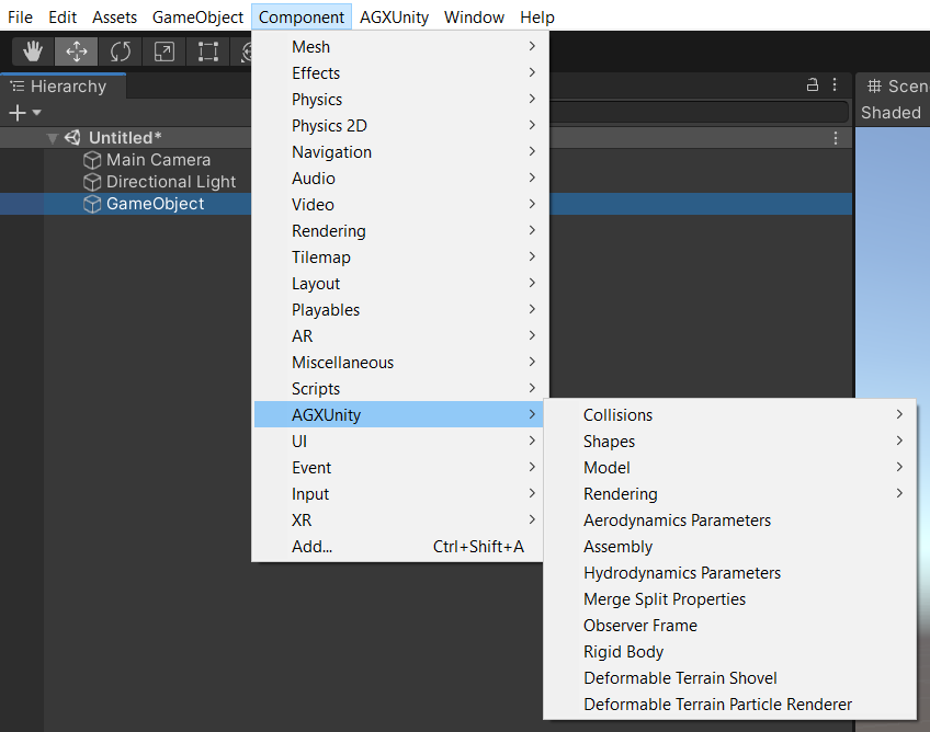
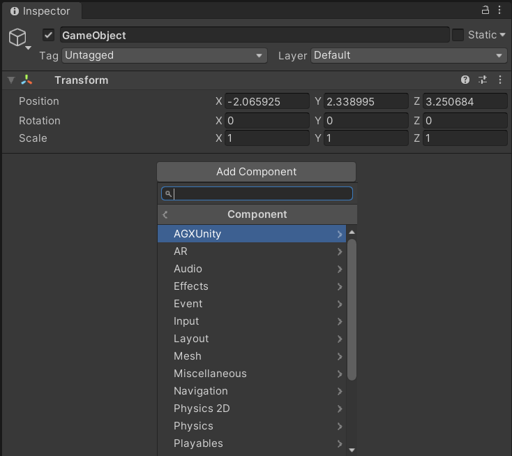
2.1.4. Component main and Inspector menus
Add component to selected game object(s).
2.2. Components
2.2.1. Shapes
Shapes defines the geometry of an object and can be of primitive types, such as sphere, capsule, box etc., or arbitrarily shaped, such as triangle mesh or height field.
Shape is base component for collision objects and all primitive and mesh shape types inherits its properties.
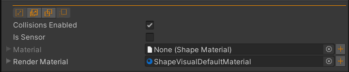
Shape properties and tools inherited by all shape types.
Property |
Description |
Default |
|---|---|---|
Collisions Enabled |
True if this shape can collide with other objects, false to disable all interactions with this shape. |
true |
Is Sensor |
True if this shape is a sensor, meaning this shape will be included in the collision detection but the resulting contacts are not passed to the solver. |
false |
Material |
Shape Material associated to this shape. |
null |
Render Material |
Render material (UnityEngine.Material) used when a visual representation has been associated with the shape, e.g., by using Create visual tool. |
null/not visible |
Tool |
Description |
Notes |
|---|---|---|
|
Resize shape in Scene View holding Ctrl for asymmetric or Ctrl+Shift for symmetric resize of the shape. See Shape resize tool for details. |
|
|
[Experimental] Create additional shapes as children to this object given visual representations. Select child visual in Scene View and follow instructions in the Inspector. |
|
|
Disable collisions between this object and objects selected in Scene View. See Disable collisions tool for details. |
|
|
Create visual representation of current context shapes. See Create visual tool for details. |
Note
Primitive shapes doesn’t support scaling of the transforms when each primitive shape has a well defined size. The more general shape Mesh supports scaling.
2.2.1.1. Box
Box collision shape which size is defined given half-extents, i.e., half-width, half-height and half-depth.
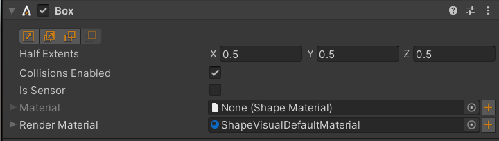
Box Inspector properties with default half-extents 0.5 x 0.5 x 0.5.
Property |
Description |
Default |
|---|---|---|
Half Extents |
Box half-extents. |
(0.5, 0.5, 0.5) |
See also
Inherited properties and tools.
2.2.1.2. Sphere
Sphere collision shape which size is defined given radius.
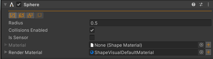
Sphere Inspector properties with default radius 0.5.
Property |
Description |
Default |
|---|---|---|
Radius |
Sphere radius. |
0.5 |
See also
Inherited properties and tools.
2.2.1.3. Capsule
Capsule collision shape which size is defined given height and radius.
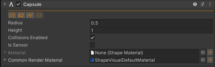
Capsule Inspector properties with default height 1.0 and default radius 0.5.
Property |
Description |
Default |
|---|---|---|
Height |
Capsule height. |
1.0 |
Radius |
Capsule radius. |
0.5 |
Note
The Inspector is showing Common Render Material instead of Render Material because the visual representation of the capsule is an assembly of three objects; top half-sphere, cylinder cap and bottom half-sphere. The three objects share the same material and changing Common Render Material will assign the new material to all three objects. If the objects don’t have common material Render Material will be a list of each individual material.
See also
Inherited properties and tools.
2.2.1.4. Cylinder
Cylinder collision shape which size is defined given height and radius.
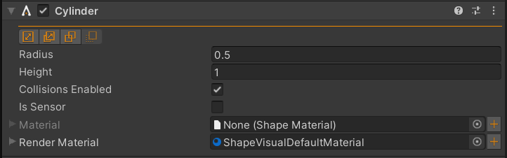
Cylinder Inspector properties with default height 1.0 and default radius 0.5.
Property |
Description |
Default |
|---|---|---|
Height |
Cylinder height. |
1.0 |
Radius |
Cylinder radius. |
0.5 |
See also
Inherited properties and tools.
2.2.1.5. Mesh
Generic mesh collision shape which surface and size is defined given a source UnityEngine.Mesh asset
and scale of the transform. Note that this AGXUnity.Collide.Mesh supports any number of source meshes,
which will be merged into a single collision mesh when initialized. Support for multiple source meshes hasn’t been
exposed in the Inspector but is accessible from scripts.
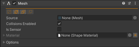
Mesh Inspector properties.
Property |
Description |
Default |
|---|---|---|
Source |
Source mesh asset. |
null |
Options |
Trimesh, vertex reduction disabled. |
See also
Inherited properties and tools.
Mesh and scale of its transform and parent transform.
2.2.1.5.1. Source read/write access is required
The Source mesh asset has to have mesh data read/write access enabled. When Unity imports models, such as
.fbx or .dae, the mesh data is protected on the GPU. This means that it’s not possible to read
the mesh data, required for the collision mesh, on the CPU.
To enable read/write, select the asset in Project View and make sure the Read/Write Enabled checkbox is
enabled in the Inspector.
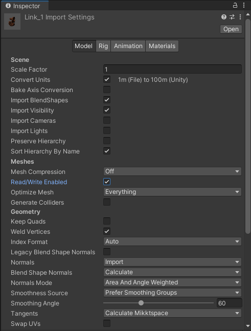
Model import settings Inspector, the Read/Write Enabled has to be checked for the collisions mesh to
be able to access the mesh data.
2.2.1.5.2. Collision Mesh Options
Applied Collision Mesh Options will separate the mesh data from the given source UnityEngine.Mesh to enable
additional non-runtime mesh operations, such as Vertex Reduction, Convex Shape and Convex Decomposition.
Applying the default options will create an exact copy of the mesh data in the source UnityEngine.Mesh.
Vertices and Triangles/Indices of a collision mesh are stored in AGXUnity.Collide.CollisionMeshData and
Mesh contains a list of these collision meshes. If the list is empty (default), the source
UnityEngine.Mesh is used, as in 2.4.3 (2021-06-17) and earlier versions.
Property |
Description |
Default |
|---|---|---|
Mode |
Collision shape(s) type: Trimesh, Convex or Convex Decomposition |
Trimesh |
Merge Nearby Enabled |
True to enable merging of nearby vertices |
false |
Merge Nearby Distance |
|
0.001 |
Vertex Reduction Enabled |
True to enable vertex reduction. |
false |
Reduction Ratio |
Reduction ratio ranging [0.02, 0.98] where lower values results in more reduced vertices. |
0.5 |
Reduction Aggressiveness |
Lower is faster and higher value results in better decimation. |
7.0 |
Element Resolution Per Axis |
Convex Decomposition - lower values results in less accurate decomposition but is faster. Higher values results in a more accurate convex representation but takes more time. Recommended range [20, 400]. |
50.0 |
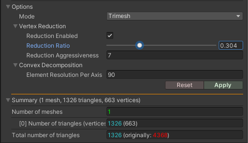
Expanded Collision Mesh Options Inspector of a Mesh with Vertex Reduction enabled at 0.3 Reduction Ratio. The “Summary” shows a reduction of triangles from 4368 to 1326.
Note
Apply will generate the collision mesh(es) given the current options. Reset will delete the current collision mesh(es) and reset the options to default.
Demonstration of mesh gears, interacting with each other by the contacts created between them.
Default, using the source UnityEngine.Mesh - vertex reduction enabled - as convexes
(bad idea for gears) and convex decompositions with Element Resolution Per Axis at 90 to catch
(almost) all cogs. Note that most of the time it took performing the convex decomposition has
been edited out. It took about 10 seconds per gear.
Note
Avoid generation of collision meshes on prefab instances. To create/modify collision meshes, open the prefab in the Prefab Stage and generate/modify the collision meshes from there. The reason for this is that Unity may hang for a long time due to the amount of Prefab Overrides the collision meshes results in on prefab instances.
2.2.1.6. Height Field
Height field is a static height map that reads the height data from an UnityEngine.Terrain instance.
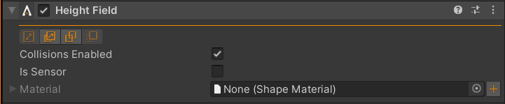
Height field Inspector properties.
See also
Inherited properties and tools.
2.2.1.7. Plane
Plane collision shape where the plane normal is the y-axis of its transform.
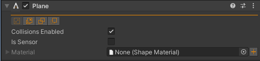
Plane Inspector properties are the default of every other shape. The plane is defined by its transform where the y-axis defines the normal in the plane.
See also
Inherited properties and tools.
2.2.1.8. Additional shapes
Note
Hollow Cylinder, Cone and Hollow Cone supports proper contact generation between each other. When colliding with other shape types a fallback is used, treating either Hollow Cylinder, Cone or Hollow Cone as a convex, generating maximum one contact point. Hollow Cylinder and Hollow Cone doesn’t have a hole either colliding with other shapes since Hollow Cylinder and Hollow Cone are converted to convex shapes.
2.2.2. Rigid Body
A rigid body is an entity in 3D space with physical properties such as mass, inertia and dynamic properties such as position, rotation and velocity.
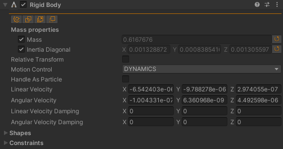
Rigid body box (1 x 1 x 1 meters) Inspector with default mass and inertia given default density 1000 \(kg/m^3\).
Property |
Description |
Default |
|---|---|---|
Mass |
Mass of the rigid body. |
1 |
Inertia Diagonal |
Inertia diagonal of the rigid body. |
(1, 1, 1) |
Motion Control |
Motion control of the rigid body. |
DYNAMICS |
Handle As Particle |
Toggle whether rotational properties of the rigid body should be disabled. |
false |
Linear Velocity |
Initial/current linear velocity of the rigid body - in world frame. |
(0, 0, 0) |
Angular Velocity |
Initial/current angular velocity of the rigid body - in world frame. |
(0, 0, 0) |
Linear Velocity Damping |
Linear velocity damping of the rigid body - in local frame. |
(0, 0, 0) |
Angular Velocity Damping |
Angular velocity damping of the rigid body - in local frame. |
(0, 0, 0) |
Tool |
Description |
Notes |
|---|---|---|
|
Configure and create constraints. |
|
|
Disable collisions between this object and objects selected in Scene View. See Disable collisions tool for details. |
|
|
[Experimental] Create additional shapes as children to this object given visual representations. Select child visual in Scene View and follow instructions in the Inspector. |
|
|
Create visual representation of current context shapes. See Create visual tool for details. |
Affects all shapes associated to the rigid body. |
2.2.2.1. Mass properties
Mass and inertia can either be calculated given current shape configuration (size, shape materials and relative transform) of the rigid body, or explicitly assigned in the Inspector.
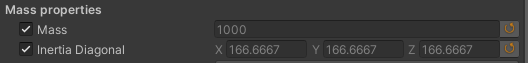
Mass properties Inspector with automatic calculation toggle, mass/inertia fields and explicit update button.
2.2.2.2. Collision shapes
Shapes can either be added to the game object the Rigid Body component is at, without relative offset, and/or as child game objects with arbitrary relative transform.
Rigid body and box components on the same game object meaning the rigid body shares the transform with the box - suitable when the shape doesn’t have a relative transform to the rigid body.
Rigid body game object with several shapes, of arbitrary relative transforms, as children.
2.2.2.3. Motion control
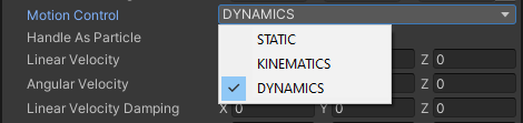
A dynamic rigid body has mass and inertia, and interacts with other objects through its Shapes and/or Constraints. Dynamics rigid bodies may have an initial linear- and/or angular velocity. The continuous velocities and transform integrations are made by the AGX Dynamics solvers.
A kinematic rigid body has infinite mass and inertia when it interacts with other objects and kinematic bodies has explicit (user defined) linear- and angular velocity.
A static rigid body has infinite mass and inertia but no linear- or angular velocity. The transform should also remain constant through a simulation.
2.2.3. Constraint
Constraint (or Joint) in AGX Dynamics for Unity defines a geometrical relation between one or two objects. Each object in the constraint has its own frame, where that frames z-axis is, by definition, the constraint axis. Several constraint types has a well defined rotation and/or translation axis and that axis is about/along the constraint axis.
Constraints could have controllers. Controllers are drivers or further limitations about/along the constraint axis.
Type |
Axis |
Controllers |
|---|---|---|
Hinge |
Rotation |
Range, Target Speed, Lock, Electric Motor, Friction |
Prismatic |
Translation |
Range, Target Speed, Lock, Electric Motor, Friction |
Lock Joint |
None |
None |
Cylindrical Joint |
Rotation and Translation |
Range, Target Speed, Lock, Electric Motor, Friction, Screw |
Ball Joint |
None |
None |
Distance Joint |
Translation |
Range, Target Speed, Lock, Electric Motor, Friction |
Angular Lock Joint |
None |
None |
Plane Joint |
None |
None |
2.2.3.1. Frames
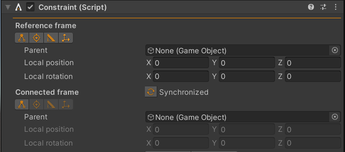
Constraint frames Inspector.
All constraints contains two frames - Reference frame and Connected frame. The reference frame is the main reference frame and by default the connected frame is synchronized to be initialized given the transform of the reference frame.
Property |
Description |
Default |
|---|---|---|
Parent |
Parent object that the frame follows when moved. |
null |
Local Position |
Local position with respect to Parent. |
(0, 0, 0) |
Local Rotation |
Local rotation with respect to Parent. |
(0, 0, 0) |
Tool |
Description |
|---|---|
|
Select parent in Scene View. |
|
Find transform given a point on a mesh surface. |
|
Find transform given a triangle edge and surface. |
|
Toggle to enable/disable the transform handle in Scene View. |
2.2.3.2. Properties
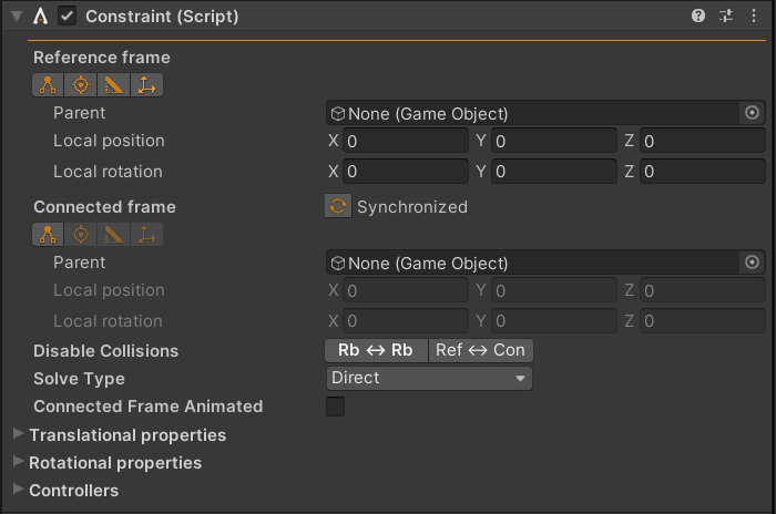
Constraint Inspector.
Property |
Description |
Default |
|---|---|---|
Reference frame |
Constraint reference frame with Parent and local transform with respect to the parent. |
|
Connected frame |
Constraint connected frame with Parent and local transform with respect to the parent. |
|
Disable Collisions |
Disable collisions between the pair of rigid bodies in the constraint or disable collisions between reference frame parent against connected frame parent - or don’t disable. |
Don’t disable collisions |
Solve Type |
Constraint solve type Direct, Direct And Iterative or Iterative. |
Direct |
Connected Frame Animated |
When true, the transform of the native connected frame is written back to the connected frame. |
false |
Translational properties |
Compliance, damping and force range of each constrained, translational degree of freedom. |
|
Rotational properties |
Compliance, damping and force range of each constrained, rotational degree of freedom. |
|
Controllers |
List of controllers if the constraint type supports controllers. |
2.2.3.3. Controllers
A constraint controller is constraining a free degree of freedom of a constraint, e.g., the rotation axis of a hinge. Each controller type inherits the following base properties:
Property |
Description |
Default |
|---|---|---|
Enable |
Toggle to enable/disable the controller. |
false |
Compliance |
Compliance of the controller. |
1.0E-8 |
Damping |
Damping of the controller. |
0.0333 |
Force Range |
The controller may only apply forces within this range. |
(-inf, inf) |
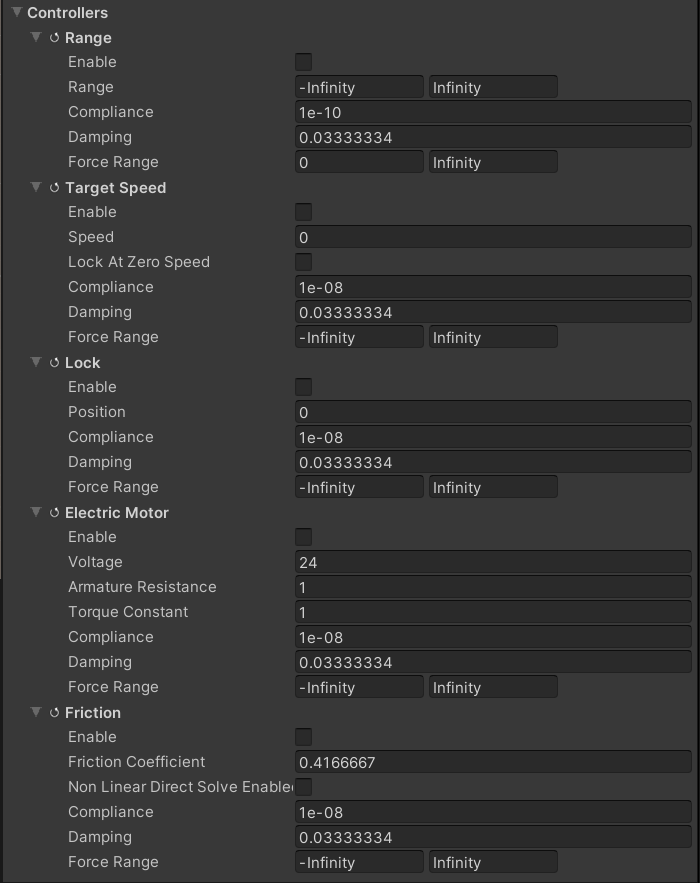
Controllers of a Hinge. This list is similar for all constraint types that has controllers except for Cylindrical Joint which has both rotational and translational controllers and an additional Screw Controller.
2.2.3.4. Configuration
When constraints normally relates to a pair of objects, the constraint component lives on its own game object where the game object transform is ignored.
Under normal conditions, configuration of a constraint can be divided into three tasks:
Find constraint (reference) frame parent and transform.
Select connected frame parent.
Assign initial values and/or enable and configure controllers.
Tools, such as Find point tool ![]() , Find edge tool
, Find edge tool ![]() and Select parent tool
and Select parent tool ![]() , can be used to complete (1) and (2).
, can be used to complete (1) and (2).
Using Find edge tool and Select parent tool to configure frames for a Prismatic and a Hinge. The Target Speed controller is enabled with 1 m/s target speed for the prismatic.
2.2.4. Wire
Wire is an adaptive resolution lumped element model for simulating wires, ropes and chains. The resolution of the wire adopts to current tension, filtering out the high frequencies when the wire is under heavy load by removing mass nodes and distributing the mass to other places along the wire. The removed nodes comes back again when/if the tension is low enough. This makes the wire model stable and accurate for a wide range of scenarios, such as heavy loads and/or extremely long (10 km or longer) where for example our fixed resolution model, Cable, will fail to perform.
See AGX Dynamics Wire documentation for further information about the wire model.
Note
Torsion is not included in the wire model.
To create a wire, add the Wire component to a game object or click
AGXUnity -> Model -> Wire from the main menu for a new game object
with the Wire component added.
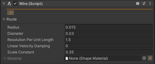
Wire Inspector with default values.
Property |
Description |
Default |
|---|---|---|
Route |
List of nodes that defines the initial route of the wire. |
|
Radius |
Radius of the wire (coupled with Diameter). |
0.015 |
Diameter |
Diameter of the wire (coupled with Radius). |
0.03 |
Resolution Per Unit Length |
Target maximum resolution of mass nodes per length unit. |
1.5 |
Linear Velocity Damping |
Velocity damping value of the wire. |
0 |
Scale Constant |
Value that indicates how likely it is that mass nodes appears along the wire. Higher value means more likely. |
0.35 |
Material |
Shape Material of the wire. |
null |
Tip
Demo Scene and Deck Crane examples.
2.2.4.1. Routing a wire
The wire route is a list of nodes where the order of the nodes is important. Read more about the different node types in the AGX Dynamics Node documentation.
The route is empty by default, the first node is added by pressing (1) in the figure below.
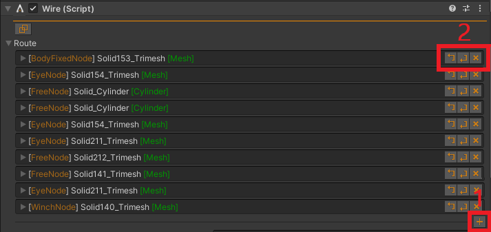
Wire route list Inspector. (1) Append new node to the list. (2) Insert node before, insert node after and erase node.
Each node in the route has a type and a frame. The frame has Select parent tool,
Find point tool, Find edge tool and toggle transform handle to manage
the transform and visualization of the node. The rotation of the node is only important for
Winch Node where the direction of the winch is along the z-axis of the node frame.
Errors in the route are marked in red and the tooltip displays the error.
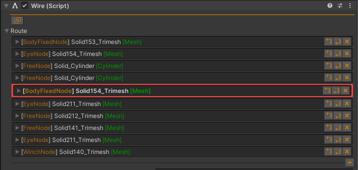
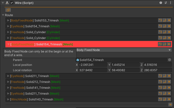
Route error displaying tooltip: Body Fixed Node can only be at the begin or at the end of wire.
Routing a wire around three cylinders and attaching a dynamic box using eye nodes (slides along the wire). The additional free node before the dynamic box is to add additional length to the route when the wire will wrap around the cylinders when the simulation starts.
2.2.4.2. Rendering the wire
The provided AGXUnity.Rendering.WireRenderer is currently an example implementation of how a wire can be rendered.
While it is supported to use any regular material with this component, it is recommended to use the Cable and Wire shader
provided in AGXUnity/Built-In or AGXUnity/Shader Graph. (See Custom AGXUnity rendering materials for more info on which shader to choose.)
This shader additionally supports texture scaling on the wire to allow for higher visual fidelity wires.
2.2.4.3. Accessing route positions through scripting
Example how collect the world positions of the route nodes:
var wire = GetComponent<Wire>();

var positions = new List<Vector3>();
foreach ( var routeNode in wire.Route )
  positions.Add( routeNode.Position );

Vector3[] alsoPositions = ( from node in wire.Route
                            select node.Position ).ToArray();
When the wire has been initialized, the route shouldn’t be accessed since there’s more data in the simulation. Collecting the world positions of all points of an initialized wire:
// Extension methods ToHandedVector3() etc.
using AGXUnity.Utils;

...

var nativeWire = GetComponent<Wire>().Native;

var positions = new List<Vector3>();
var currIterator = nativeWire.getRenderBeginIterator();
var endIterator = nativeWire.getRenderEndIterator();
while ( !currIterator.EqualWith( endIterator ) ) {
  positions.Add( currIterator.getWorldPosition().ToHandedVector3() );

  // Incrementing the iterator on the native side to avoid
  // creating garbage.
  currIterator.inc();
}

// Pooling iterators to avoid garbage.
currIterator.ReturnToPool();
endIterator.ReturnToPool();
2.2.4.4. Cutting and merging wires
One key difference between cables and wires is the ability to cut and merge wires at runtime. To facilitate this process, AGXUnity provides a scripting API to the wire component that manages the wire components to ensure that new components are created when cutting, and old components are destroyed when merging.
var result = SourceWire.Cut( Vector3.zero );
if( result == null )
   Debug.LogError( "Cutting failed!" );

if( !SourceWire.Merge( result ) )
   Debug.LogError( "Merging failed!" );
This sample code cuts the SourceWire into two wires at the point on the wire closest to the world origin
and places the end half of the wire into a new Wire Component on the returned GameObject.
The second wire is then merged into the original wire again and the newly created component and object is destroyed.
There are some considerations to take into account when using the Cut/Merge-API:
The ordering of the wires matters.
When cutting, the original object will always keep the nodes closest to the beginning of the wire while placing the second half into the returned, newly created wire.
When merging, the end of the source wire will be merged to the beginning of the provided wire.
Winches might be moved into new objects.
When cutting a wire with winches, the begin winch will remain in the original wire component while the end winch will be moved into the newly created component.
When merging, the merged ends are not allowed to contain winches. If any of the wires does contain winches on the merged wire-ends, the merge will fail and return
false.When merging, the distance between the end of the merged-into-wire and the beginning of the merged wire will be filled with newly created wire. This means that if the ends of the two wires are not positioned on top of each other, the merged wire will be longer than the two parts.
2.2.5. Cable
The cable module is used to simulate cables, hoses, ropes, short wires and dress packs. These are long structures with a circular cross section that can be bent, stretched and twisted.
See AGX Dynamics Cable documentation for more information about the cable module.
To create a cable, add the Cable component to a game object or click
AGXUnity -> Model -> Cable from the main menu for a new game object with the
Cable component added.
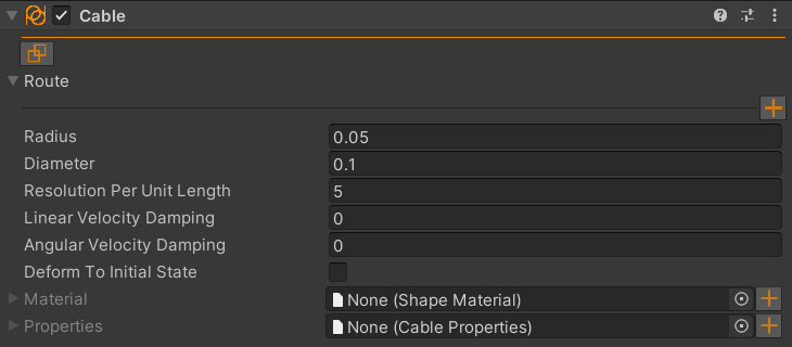
Cable Inspector with default values.
Property |
Description |
Default |
|---|---|---|
Route |
List of nodes that defines the initial route of the cable. |
|
Radius |
Radius of the cable (coupled with Diameter). |
0.05 |
Diameter |
Diameter of the cable (coupled with Radius). |
0.1 |
Resolution Per Unit Length |
Target maximum resolution per length unit. |
5.0 |
Linear Velocity Damping |
Linear velocity damping value of each cable element. |
0 |
Angular Velocity Damping |
Angular velocity damping value of each cable element. |
0 |
Deform To Initial State |
By default, a routed cable will try to straighten it self out, i.e. the resting state is a straight, untwisted cable. When enabled, this option rebinds the resting state after the routing algorithm is run so that the cable will attempt to preserve the initial state instead. |
false |
Material |
Shape Material of the wire. |
null |
Properties |
Cable Properties of the cable. |
null |
Tip
Demo Scene example.
2.2.5.1. Routing the cable
Routing a cable is very similar to routing a wire but since the cable model includes torsion, the complete transform of the node is important and the direction of the cable is by definition along the z-axis of the frame.
Another discrepancy from the Wire is there may be any number of fixed nodes along a cable.
Note
The frame tools around routing of cables aren’t currently optimal. The workflow of routing cables will be improved in the future.
2.2.5.2. Cable Damage
Cable Damage is a module that can calculate, aggregate and visualize forces and stress
acting on the cable. Adding a CableDamage component to a GameObject with a Cable
component will enable cable damage for the cable. The damage calculations and visualizations are configured with
a Cable Damage Properties asset.
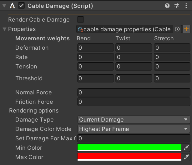
Cable Damage Inspector with default values.
See AGX Dynamics Cable Damage documentation for in-depth information on the cable damage system and how to configure it.
It is up to the user to create scripts to utilize the generated damage data as desired. The total or the
current damage for each segment can also be visualized directly. To do this, there needs to be an
active CableRenderer component on the same GameObject. The rendering is then enabled with
the Render Cable Damage setting on the component. An example is shown below.

Sample cable with damage configured to rely 100 % on bending deformation.
The Cable Damage visualization is configured on the Cable Damage Properties asset.
2.2.5.3. Cable Tunneling Guard
Cable Tunneling Guard is a component which can help reduce the occurrence of tunneling between instances of cable segments. It works by monitoring contacts with hulls created around the cable to predict future contacts. This functionality is customizable using some different parameters which can found more closely described in the AGX Dynamics documentation.
The aforementioned hulls around the cable can be rendered using the gizmo rendered by the script to provide a visualization of the operating range of the component.
2.2.5.4. Cable Rendering
AGXUnity provides two different renderers as examples of how a cable can be rendered.
AGXUnity.Rendering.CableRenderer is currently the simplest
option which renders the cable with the DrawMeshInstanced method for performance. This requires a graphical Material that has the option Enable GPU Instancing enabled.
While it is supported to use any regular material with this component, some features such as visualization of the damage
calculated by the Cable Damage component requires the use of the Cable and Wire shader provided in AGXUnity/Built-In
or AGXUnity/Shader Graph. (See Custom AGXUnity rendering materials for more info on which shader to choose.)
This shader additionally supports texture scaling on the cable to allow for higher visual fidelity cables.
The second renderer provides an alternative rendering method through a Unity SkinnedMeshRenderer. This renderer additionally requires a mesh to be defined so that
the segments of the cable can be used as bones for deforming it. This renderer is easily combined with the workflow of the Route from mesh tool
to combine the visual of a mesh with a route generated from the mesh itself.
Note
Skinned cable rendering does not currently support rendering cable damage, unlike the CableRenderer component.
Warning
The SkinnedCableRenderer does not perform any kind of remeshing to ensure a good subdivision level
for the mesh. As such is is important to ensure that the mesh is properly subdivided with triangles
being smaller than the cable segments for the skinning to give the best visual results.
2.2.6. Deformable Terrain
Deformable Terrain, AGXUnity.Model.DeformableTerrain, module is a deformable
surface enabling objects to perform different operations - such as compressing,
digging, pushing/pulling and grading.
See AGX Dynamics Terrain documentation for detailed information about the terrain module.
Note
Currently, the Deformable Terrain component depends on
UnityEngine.Terrain which is required to be static, while
the AGX Dynamics Terrain module supports dynamic/moving terrains.
To create a Deformable Terrain, add the Deformable Terrain component to
a UnityEngine.Terrain game object or click AGXUnity -> Model -> Deformable Terrain
from the main menu for a new UnityEngine.Terrain game object with the
Deformable Terrain component added. The latter will create a 60 square
meter UnityEngine.Terrain with a 257 x 257 height map resolution.
The Terrain width and length with the height map resolution defines the size of the particles while digging. 60 square meters with a 257 x 257 resolution results in a nominal radius of 0.127 meters of the particles.
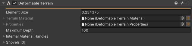
Deformable Terrain Inspector with default values (Element Size is dependent on terrain width, length and resolution and cannot be changed).
Property |
Description |
Default |
|---|---|---|
Default Terrain Material |
The default Deformable Terrain Material of the terrain. |
null |
Terrain Properties |
Deformable Terrain Properties of the terrain. |
null |
Maximum Depth |
Maximum depth possible to dig/deform, see Initialization for further information. |
20.0 |
Internal Material Handles |
Provides a way to reference the internal Shape Material of the terrain and it’s particles in Contact Material. |
null |
Note
The parameters set in Surface Material and Particle Material under Internal Material Handles are not used by the terrain. Instead these parameters are overwritten based on the parameters set in the Deformable Terrain Material. For this reason it is not recommended to use the same materials for other shapes. The purpose of these materials is to be a handle to use when creating contact materials between terrain objects and external objects.
Tip
Wheel Loader on Terrain example.
2.2.6.1. Initialization
When compacting, digging, pushing/pulling and grading the deformable terrain, the
heights in the UnityEngine.TerrainData object are updated, and these changes
are normally persistent. To prevent the height data from being persistent, Deformable
Terrain is storing the initial heights during initialize and writing them back to the
UnityEngine.TerrainData object during uninitialize. As a result of this, the data could be
lost/left modified if the application exists without proper uninitialization, e.g., due to a crash.
The Unity terrain doesn’t support negative height values and normally one don’t
want to raise the whole terrain (using the Unity terrain tools) to be able to
dig in the Deformable Terrain. Deformable Terrain solves this by, during initialization,
adding Maximum Depth to all height values and compensating the height
difference by changing the position of the terrain game object Maximum Depth
down. The change of the transform is restored to the original during uninitialization.
The change of the transform is made during runtime so the transform will always be restored,
even after a crash, but the transform could seem wrong due to the initially changed
height values in case of a crash.
Note
Make sure the Terrain Height property under
Terrain Settings -> Mesh Resolution is large enough to handle
the addition of height made during initialization. E.g., if the hills in
the terrain is expected to be at maximum 15 meters high and Maximum Depth
is 20 meters, Terrain Height should be at least 15 + 20 = 35 meters.
2.2.6.2. Shovel
A “Shovel” is any object that can represent a tool used in earthmoving operations - from an excavator or wheel loader bucket to a bulldozer blade.
See AGX Dynamics Terrain Shovel documentation for detailed information about the shovel.
The Deformable Terrain Shovel component requires a game object with the Rigid Body
component.
Debug.Assert( bucketGameObject.GetComponent<AGXUnity.RigidBody>() != null );
var shovel = bucketGameObject.AddComponent<AGXUnity.Model.DeformableTerrainShovel>();
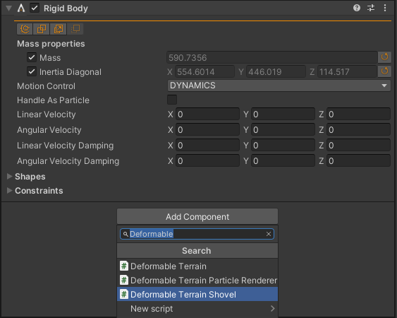
Adding the Deformable Terrain Shovel component to a game object with a Rigid Body component.
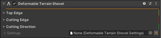
Deformable Terrain Shovel Inspector with default values.
Property |
Description |
Default |
|---|---|---|
Top Edge |
Top edge of the shovel. |
unconfigured |
Cutting Edge |
Cutting edge of the shovel. |
unconfigured |
Has Teeth |
Whether or not the shovel has teeth. |
False |
Tooth Direction |
The direction of the shovel’s teeth |
unconfigured |
Settings |
Deformable Terrain Shovel Settings of the shovel. |
null |
2.2.6.3. Rendering the particles
The simulated spheres generated from the Deformable Terrain aren’t particles, they’re 6 DOF, so
rotation may be taken into account. The included Deformable Terrain Particle Renderer is
rendering the particles, including rotation, given a unit size object to instantiate.
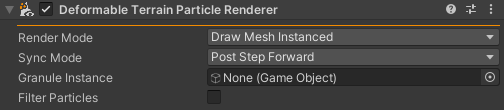
Deformable Terrain Particle Renderer Inspector with default values.
Property |
Description |
Default |
|---|---|---|
Render Mode |
Draw Mesh Instanced or Game Object where Draw Mesh Instanced is using
|
Draw Mesh Instanced |
Sync Mode |
Whether to update the data for the rendered particles on each update or after the simulation steps |
Post Step Forward |
Granule Instance |
Game Object of unit size containing the visual data. For Draw Mesh Instanced it’s
required that Game Object contains one |
null |
Filter Particles |
When enabled, this renderer will only render particles that correspond to it’s parent terrain. |
False |
Warning
When the Filter Particles option is enabled, each renderer still have to iterate all particles in the simulation. As such, enabling this option might incur some performance overhead.
Example how to update the transforms of the instances:
var soilSimulation = DeformableTerrain.Native.getSoilSimulationInterface();
var granulars      = soilSimulation.getSoilParticles();
var numGranulars   = (int)granulars.size();

// More granular instances comparing to last time, create
// more instances to match numGranulars.
if ( numGranulars > transform.childCount )
  Create( numGranulars - transform.childCount );
// Less granular instances comparing to last time, destroy.
else if ( transform.childCount > numGranulars )
  Destroy( transform.childCount - numGranulars );

Debug.Assert( transform.childCount == numGranulars );

for ( int i = 0; i < numGranulars; ++i ) {
  var granule  = granulars.at( (uint)i );
  var instance = transform.GetChild( i );
  instance.position = granule.position().ToHandedVector3();
  instance.rotation = granule.rotation().ToHandedQuaternion();

  // Assuming unit size of the instance, scale to diameter
  // of the granule.
  instance.localScale = Vector3.one * 2.0f * (float)granule.getRadius();

  // Return the proxy class to the pool to avoid garbage.
  granule.ReturnToPool();
}
Creating a deformable terrain particle renderer with different granules.
2.2.6.4. Upsampling Particle Renderer
Another form of rendering terrain particles available in AGXUnity is the AGXUnity.Rendering.UpsamplingParticleRenderer.
This renderer uses the simulated particles to instantiate and displace a larger amount of smaller
particles completely contained on the GPU. This allows for higher granularity rendering without
increasing the simulation complexity.
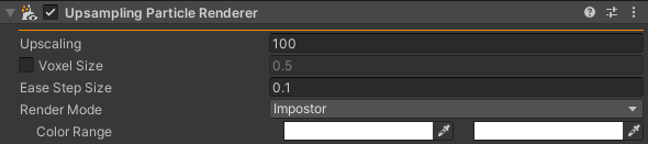
Upsampling Particle Renderer Inspector with default values.
Property |
Description |
Default |
|---|---|---|
Upscaling |
The desired upscaling factor which the renderer will try to achieve. |
100 |
Voxel Size |
The size of the grid voxels constructed by the renderer. If unchecked, the element size of the parent terrain is used |
0.5 (Unchecked) |
Ease Step Size |
This controls how quickly the particles are eased in/out when spawned/destroyed, |
0.1 |
Render Mode |
Impostor renders the particles as impostor spheres, while Mesh renders them as instanced meshes. |
Impostor |
Color Range |
When using the Impostor rendering mode, this controls the color range of the small particles. |
White - White |
Granule Mesh |
The mesh to render when using the Mesh rendering mode. |
Resources/Debug/Models/Icosahedron |
Granule Material |
The material to render when using the Mesh rendering mode. |
AGXUnity/Built-In/Upsampled Particle (Surface) |
This renderer constructs a voxel grid containing mass and velocity contributions from nearby simulated particles. These voxel grids are then used to spawn, destroy and move smaller particles. Since these particles reside only on the GPU, custom shaders need to be employed to render the smaller particles.
In the Built-in render pipeline there are two options: Construct impostor spheres from the particle positions or render instanced meshes at each of the particle positions. When using HDRP or URP, only the Mesh option is supported. In general, the Impostor option is faster and renders smoother spheres but allows for less customization of the rendered particles.
To create custom materials for the Mesh rendering option, the AGXUnity/Shader Graph/Upsampled Particle
or AGXUnity/Built-In/Upsampled Particle shaders should be used. (See Custom AGXUnity rendering materials for more info on which shader to choose.)
These currently only support a limited subset of surface options but could be extended to support additional if required.
2.2.6.5. Using different terrain materials
Sometimes, it is desirable to be able to simulate different materials in different parts of the
Deformable Terrain. To enable this, a GameObject containing a AGXUnity.Model.TerrainMaterialPatch
can be added as a child object to the terrain.
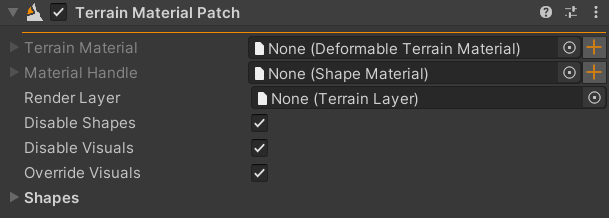
Terrain Material Patch Inspector with default values.
Property |
Description |
Default |
|---|---|---|
Terrain Material |
The Deformable Terrain Material to associate with this patch. |
null |
Material Handle |
A reference to a Shape Material to use in contact materials between this patch and other objects. |
null |
Render Layer |
A Unity Terrain Layer used to render the material associated with this patch in the parent terrain |
null |
Disable Shapes |
When enabled, collisions are disabled for child Shapes. |
true |
Disable Visuals |
When enabled, Visual components are disabled for child Shapes. |
true |
Override Visuals |
When enabled, the visual components in the child shapes will be overridden with a default material |
true |
When the simulation is started, each patch adds the corresponding Deformable Terrain Material to it’s parent terrain and associates the set Shape Material, if any. After adding the materials, any Shapes that are children to the TerrainMaterial Patch are iterated and the parts overlapping the parent terrain is set to the Deformable Terrain Material of the patch.
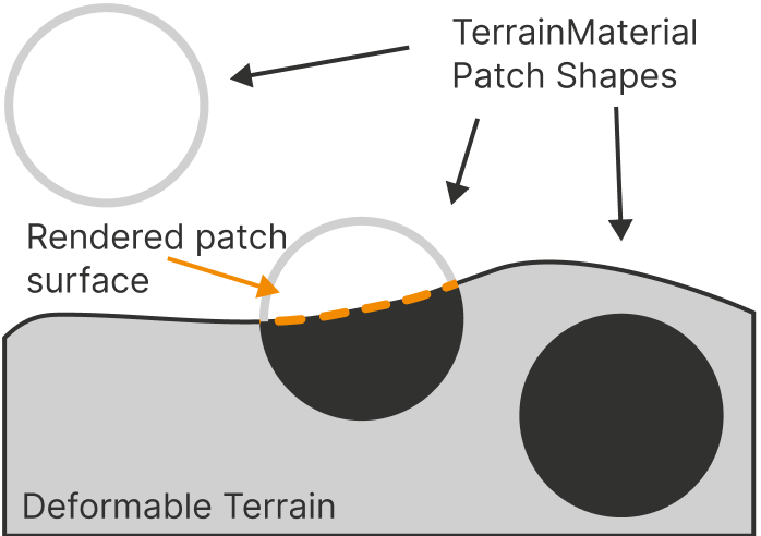
An illustration of the Terrain Material assignments based on patches. Note that only parts of the patches that intersect the terrain are set.
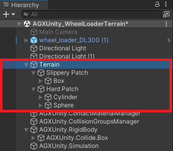
An example hierarchy with a terrain with three materials, one default and two patches with corresponding shapes.
Warning
When using terrain material patches with the Deformable Terrain Pager, the material patches has to be fully configured before the affected tiles are paged in or the materials will not be applied properly.
When using multiple different terrain materials, it is common to want to render the terrain differently based on the terrain material used.
For this reason there is a AGXUnity.Rendering.TerrainPatchRenderer which maps terrain materials to Unity Terrain Layers.
By default the Renderer fetches the corresponding Terrain Layers from the AGXUnity.Model.TerrainMaterialPatch instances that are children
to the terrain, however, it is also possible to explicitly specify a mapping in the Renderer for materials which do not contain an AGXUnity patch such as
materials which are assigned dynamically in scripts. In general, when a terrain cell is updated, the rendering is updated based on the following priority:
Explicit mapping > Implicit mapping > Default Layer.
Warning
The Terrain Patch Renderer will try it’s best to reset the TerrainData on application shutdown. This is however, not always possible so make sure that the TerrainData (terrain asset) for the terrain is backed up before using the Terrain Patch Renderer.
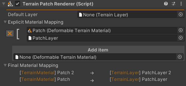
Terrain Patch Renderer Inspector with one implicit mapping (Patch 2 -> PatchLayer 2) and one explicit mapping (Patch -> PatchLayer).
Property |
Description |
Default |
|---|---|---|
Default Layer |
The Terrain Layer used to render material without mapping |
null (First Terrain Layer on Terrain) |
Explicit Material Mapping |
An explicit mapping from Deformable Terrain Material to Unity Terrain Layers which is prioritized over the implicit mapping |
|
Final Material Mapping |
A list of mapped materials and layers, any materials not in the list will be mapped to the default layer |
- |
2.2.6.6. Clamshell Buckets
Due to how the internal excavation algorithms work, issues might arise when two buckets interact such as is the case
when modelling clamshell buckets. To allow for this type of setup, the AGXUnity.Model.ClamshellBucket
component allows for specifying two shovels that are automatically merged when they are within the “closed threshold”
of each other.
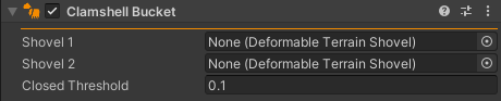
Clamshell Bucket Inspector with default values.
2.2.6.7. Soil failure volumes
In addition to using shovels to excavate the terrain it is sometimes necessary to
manually convert parts of the terrain into dynamic mass. To accommodate this need
there is a Deformable Terrain Failure Volume component which triggers soil
failures in the Shapes on the parent GameObject.
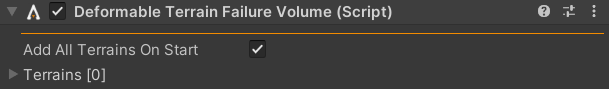
Deformable Terrain Failure Volume Inspector with default values.
Property |
Description |
Default |
|---|---|---|
Add All Terrains On Start |
Whether or not to add all Deformable Terrains to the Terrains list on startup. |
true |
Terrains |
The terrains on which to trigger soil failure. |
Note
When dynamically adding terrains to the scene, the terrains have to be manually
added to the Deformable Terrain Failure Volume as soil failures are only
triggered on added terrains.
Creating a deformable terrain failure volume.
2.2.6.8. Manipulating the terrain in scripts
The terrain components can be manipulated through C# scripting via the Get/SetHeight(s) family of methods. These methods use both the simulated AGX terrain as well as the visual Unity terrain component to ensure that the two are kept in sync.
These functions are meant to be as similar to the corresponding Unity TerrainData methods. As such the indices provided are the Unity terrain indices which are converted internally to the corresponding AGX index. To find the Unity index from a world position the offset position to the terrain is calculated after which the index is found by dividing the X and Z components by the corresponding terrain sizes and multiplying by the resolution of the terrain:
Vector3 localPosition = worldPosition - terrain.transform.position;
int xIndex = (int)(localPosition.x / terrain.TerrainData.size.x * (terrain.TerrainDataResolution - 1));
int yIndex = (int)(localPosition.z / terrain.TerrainData.size.z * (terrain.TerrainDataResolution - 1));

terrain.SetHeight(xIndex, yIndex, 1.0f);
Tip
Terrain manipulation example.
When using the Deformable Terrain Pager component, the index is calculated the same way. However, since the terrain might use different Unity terrains the index is relative to the Unity terrain on which the main Deformable Terrain Pager component is attached.
Note
Because of how the Deformable Terrain Pager tiles are connected to the Unity terrain tiles, setting the heights in a large patch of terrain can be relatively slow compared to when using the regular Deformable Terrain. For this reason it is not recommended to use the manipulation methods on the Deformable Terrain Pager every update.
Note
Deformable Terrain supports calling the manipulation methods before the terrain has been initialized. In this case, the method will simply call the corresponding Unity methods and set the height on the Unity terrain. The Deformable Terrain Pager, however, does not support this functionality.
2.2.7. Deformable Terrain Pager
The Deformable Terrain Pager component allows a large Unity terrain to be split into multiple simulated Deformable Terrain tiles. The tiles are lazily loaded when they are needed and are paged out to disk when they are not. This is useful when a large terrain should be simulated with fine-grained resolution, which would result in unmanageable data sizes using the standard Deformable Terrain. Additionally the Deformable Terrain Pager allows for the use of non-square terrains by connecting multiple Unity Terrain tiles into the desired shape.
Note
The terrain pager is only operating on the Deformable Terrain component. It will not manage load/unload of the associated Unity terrains.
To create a Deformable Terrain Pager, add the Deformable Terrain Pager Component to a
UnityEngine.Terrain game object or click AGXUnity -> Model -> Deformable Terrain Pager
from the main menu for a new UnityEngine.Terrain game object with the Deformable Terrain Pager
component added. The latter will create a 120 meter square with a 512 x 512 resolution height map resolution.
The Deformable Terrain Pager mostly uses the same parameters as the Deformable Terrain component with some additions specific to the paging procedure.
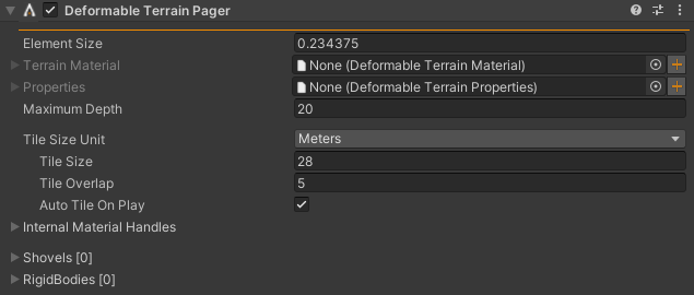
Deformable Terrain Pager Inspector with default values.
Property |
Description |
Default |
|---|---|---|
Default Terrain Material |
The default Deformable Terrain Material of the terrain. |
null |
Terrain Properties |
Deformable Terrain Properties of the terrain. |
null |
Maximum Depth |
Maximum depth possible to dig/deform |
20.0 |
Tile Size Unit |
The unit used when specifying the size of the underlying |
Meters |
Tile Size |
The size of the underlying tiles |
28.0 |
Tile Overlap |
The overlap between adjacent tiles |
5.0 |
Auto Tile On Play |
Whether to recalculate the Tile Size and Tile Overlap parameters as to fully tile the root |
true |
Internal Material Handles |
Provides a way to reference the internal Shape Material of the terrain and it’s particles in Contact Material. |
null |
Shovels |
Shovels associated to the terrain. |
|
Rigid bodies |
Rigid bodies associated to the terrain. |
2.2.7.1. Initialization
When the terrain pager is initialized it finds all terrain neighbors connected
to the UnityEngine.Terrain on the parent game object. While the same
considerations noted in the Deformable Terrain Initialization
section applies to the terrain pager initialization as well, the method is slightly different.
In order to avoid the potentially expensive operation of writing offset terrain
data upfront, a runtime AGXUnity.Model.DeformableTerrainConnector component is added to each
connected terrain tile. This component performs the deformable terrain
initialization/uninitialization procedure on demand for specific tiles. This does,
however, mean that some terrain tiles will be offset while others are not during runtime.
In addition to the depth offset procedure, the terrain pager will recalculate it’s
parameters during the initialization stage if the Auto Tile On Play option is enabled.
Note
A Deformable Terrain Pager component has to be unique in the UnityEngine.Terrain and all its connected tiles. Initialization will fail if another Deformable Terrain Pager and/or Deformable Terrain is found. Check the Deformable Terrain Pager Inspector for detailed information which other components are causing the error.
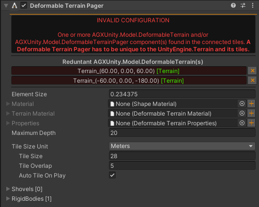
Deformable Terrain Pager Inspector when there are conflicting components in one or more of the terrain tiles.
2.2.7.2. Tile Size
Two fundamental parameters of the deformable terrain pager is the Tile Size and the
Tile Overlap. These parameters configure how the deformable terrain pager places the
underlying simulated tiles. The Tile Size parameter specifies the size of
the simulated tiles while the Tile Overlap parameter specifies the overlap
at which to place the simulated tiles. The overlap is used to improve the simulation
result by making sure that a terrain/shovel interaction can be fully contained in a
single simulated tile. As such, it is recommended to choose an overlap which is
larger than the largest interaction expected in the scene.
For more details on the size and overlap parameters, please refer to the AGX Dynamics Terrain Pager documentation.
Note
In the C++ API the size and offset parameters are specified in number of elements while the inspector property offers the ability to use either element count or absolute size in meters.
The terrain pager will not create “partial tiles” where part of the tile does not map to a Unity Terrain tile. As such, it is recommended to choose tile size and overlap such that the simulated tiles completely fill the underlying Unity terrain. As the process of finding good parameters for the terrain pager can require quite a lot of trial and error, there is a built in utility for automatically calculating decent tiling parameters based on the current parameters.
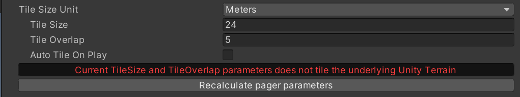
Warning in inspector when size parameters does not tile Unity terrain
2.2.7.3. Tracked Bodies
To determine which deformable terrain pager tiles that should be paged in and
which should be stored on disk, the terrain pager keeps track on a set of
Deformable Terrain Shovels and Rigid bodies.
Each tracked body specifies two radii which trigger the loading of terrain tiles
overlapping the radii. These radii are the Preload Radius and the
Required Radius. The preload radius specifies the radius at which to start
loading in simulated tiles from disk or the Unity terrain. Preloaded tiles are not
required to be available during the current time step but is loaded on a background
thread and added to the simulation when ready. This is in contrast to tiles within
the required radius which specifies that the simulation should wait until the tile
is loaded.
Note
Due to how the terrain height data is gathered from the Unity terrain, the initial terrain data fetch will fail. In order to mitigate this the preload radius should be set to at least make a preload fetch before a required fetch or there will be a time step where a required tile is not yet loaded.
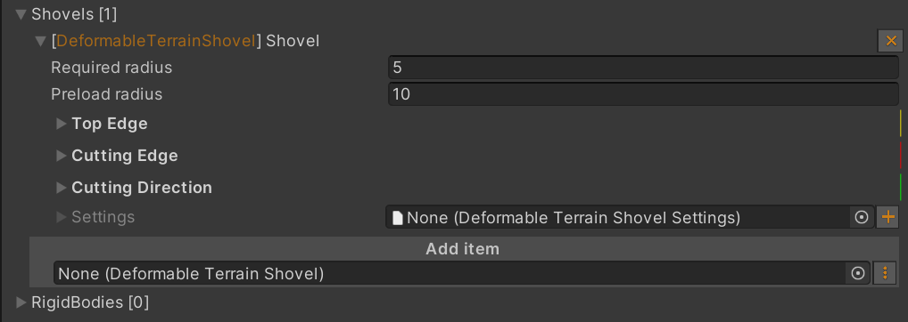
Inspector view of tracked shovels with required and preload radii.
2.2.8. Movable Terrain
The Movable Terrain module, AGXUnity.Model.MovableTerrain, is separate
terrain component which is meant for cases where a Deformable Terrain
additionally needs to be moved during runtime. Under the hood, the component uses
the same native component as the Deformable Terrain but uses a simple
unity Mesh Filter/
Renderer to work around
the limitations on Unity’s Terrain Tiles
Note
While the movable terrain avoids the limitations of Unity’s terrain module, it does also mean that the internal rendering optimizations that Unity performs when rendering terrain tiles are not used when rendering movable terrain tiles. For this reason, it is advisable to only use the movable terrain if the regular Deformable Terrain cannot be used and to limit the usage of the MovableTerrain module to small patches of terrain
To create a Movable Terrain, add the AGXUnity.MovableTerrain component to
a game object with a UnityEngine.MeshFilter and a UnityEngine.MeshRenderer,
or click AGXUnity -> Model -> Movable Terrain from the main menu for a
new game object with the AGXUnity.MovableTerrain component as well as mesh components added.
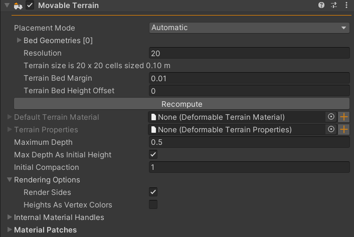
Movable Terrain Inspector with default values.
Property |
Description |
Default |
|---|---|---|
Placement Mode |
Specifies how to position the terrain. See Placement mode for more information. |
Automatic |
Size Units |
The unit used to specify the size of the terrain. |
Meters |
Size |
If Meters is the selected size unit this specifies the total size of the terrain in meter.s |
2x2 |
Resolution |
The total amount of cells which should cover the X-axis of the terrain. The Y-resolution and element size is calculated based on this value if Meters is used. |
20 |
Count |
If Cell Count size unit is used, this specifies the amount of cells in the terrain. |
20x20 |
Bed Geometries |
The scene geometries to use to create the terrain bed when the Automatic placement mode is used. |
Empty |
Terrain Bed Margin |
Adds a margin to the terrain when using the Automatic placement mode is used. |
0.01m |
Terrain Bed Height Offset |
Adds a height offset to the terrain bed when Automatic placement mode is used. |
0m |
Element Size |
The side length of each individual cell. |
0.1 |
Default Terrain Material |
The default Deformable Terrain Material of the terrain. |
null |
Terrain Properties |
Deformable Terrain Properties of the terrain. |
null |
Maximum Depth |
Maximum depth possible to dig/deform. |
0.5 |
Max Depth As Initial Height |
When enabled, the Maximum Depth of the terrain will be added to the height at each point during initialization and the effective max depth will be set to 0. |
true |
Internal Material Handles |
Provides a way to reference the internal Shape Material of the terrain and it’s particles in Contact Material. |
null |
Render Sides |
When enabled, the sides of the terrain will be rendered down to the minimum height of the terrain. This can cause some visual inconsistencies at the edges for lower resolutions and requires some extra processing during update. |
True |
Heights As Vertex Colors |
When enabled, the generate mesh will contain non-white vertex colors, see Rendering the terrain. |
False |
Note
While the Cell Count sizing mode provides exact sizing the Meters mode is approximate for the Y-axis. The reason for this is that the underlying cells are required to be square which makes it impossible to create exact cell counts for both axes in most cases.
Note
Size and Count are not used directly when Placement Mode is set to automatic but are instead calculated based on the provided Bed Geometries. Resolution, however, is used.
2.2.8.1. Initialization
While the underlying native component is the same between the AGXUnity.MovableTerrain
and the AGXUnity.DeformableTerrain there are some differences in the initialization
procedure. For one, the AGXUnity.MovableTerrain component gives the user greater
control over the properties of the agxTerrain.Terrain tile as the limitations
of the UnityEngine.Terrain does not apply to it. This gives the user a means
to specify the width, height` and importantly, the Element Size of the terrain
directly without having to go through the UnityEngine.Terrain settings.
Furthermore, since the limitations on negative heights described in Deformable Terrain Initialization
does not apply to the Mesh components used in the AGXUnity.MovableTerrain,
the initialization procedure described is not performed for the AGXUnity.MovableTerrain.
Note that this means that the UnityEngine.Transform of the AGXUnity.MovableTerrain
will not be offset by the Maximum Depth of the terrain.
Note
The AGXUnity.MovableTerrain component is treated as a Shapes
to uniformly handle AGXUnity.MovableTerrain components being added to
parent Rigid Body components.
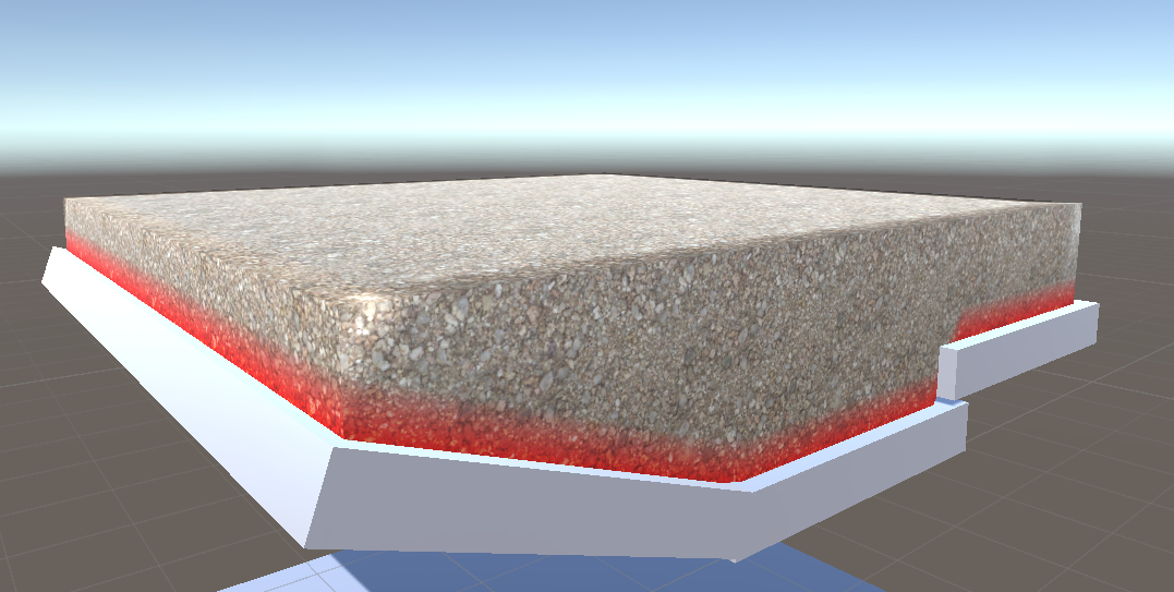
2.2.8.2. Placement mode
One common use case for the movable terrain component is to simulate dump truck beds. The Automatic placement mode is intended to make modelling these terrains easier by allowing automatic calculation of terrain size and placement given the geometries that make up the bed. This mode additionally sets minimum height limits to the terrain to avoid digging into the terrain below the base level of the bed for non-flat beds. The general workflow for using the Automatic placement mode is as follows:
Identify the parts of the model that make up the bed
Create Shapes for the bed if they do not already exist. These could be complex mesh geometries or simple box approximations. * If the collision shapes are not required for the rest of the simulation, the collision of these shapes can be disabled.
Add a movable terrain component as a child object to the bed Rigid Body.
Add the shapes from step 2 to the movable terrain Bed Geometries list.
Set the resolution of the terrain to the desired fidelity.
(optional) Set the margin and height offsets to account for any edges an z-fighting.
2.2.8.3. Rendering the terrain
One downside to using the AGXUnity.MovableTerrain component over the AGXUnity.DeformableTerrain
is that Unity’s built-in terrain tools does not support mesh components. This means that
to texture the AGXUnity.MovableTerrain GameObjects, the same procedure is used
as for any other mesh. To make this process easier the UV coordinates on the mesh filter
is set to change by one unit per meter in the world. This means that tiling textures can
be used as if each tile is 1x1 meter.
Note
When setting up terrain layers the tiling options specify the size per tile
while when setting up regular materials the option instead specify a multiplier
to the texture coordinate. To achieve the same scale, 1/layerSize
should be used when specifying material tiling.
To more easily allow for customized rendering of the terrain, the Heights As Vertex Colors easily provides height data for use in custom shaders. When this option is enabled, the vertex colors of the generated terrain mesh will include the following height data:
R - The current height.
G - The minimum height.
B - The current height above the minimum height.
An example of using the custom vertex colors do display a gradient when relative terrain heights are close to 0.
2.2.9. Track
Continuous track is part of the AGX Dynamics agxVehicle module.
See AGX Dynamics Track documentation for detailed information about track wheel, track and properties.
To create a Track, add the Track component to a game object or
click AGXUnity -> Model -> Track for a new game object with the
Track component added.
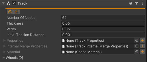
Track Inspector with default values.
Property |
Description |
Default |
|---|---|---|
Reference Object |
An object which defines the reference frame which the track is attached to. Normally, this body should be the chassis of the vehicle. |
null |
Full DoF |
When enabled, the track will simulate individual links in the track based on the track properties. |
False |
Number Of Nodes |
The number of nodes/shoes of the track. |
64 |
Thickness |
Thickness of the track. |
0.05 |
Width |
Width the track. |
0.35 |
Initial Tension Distance |
Initial node separation of the track nodes. |
1.0E-3 |
Properties |
Track Properties of the track. |
null |
Internal Merge Properties |
Track Internal Merge Properties of the track when using the FullDoF model. |
null |
Material |
Shape Material of the track. |
null |
Wheels |
Wheels associated to the track. |
|
Thickness/Width Variation |
Specifies a periodic variation to apply to the track belt links. These are purely visual when the Low DoF model is used |
None |
Creating and configuring a track using available tool to select track wheels and adding the track wheel to the Track instance, using Scene View. If the selected object doesn’t have a Track Wheel component, the component is added to the Rigid Body game object.
Creating and configuring a track using individual components.
Tip
Demo Scene example.
2.2.9.1. Track Wheel
The Track Wheel component is used by Track instances as an implicit definition of the geometry of the wheel. It contains a frame where the direction of the axes are important. For more information, read the AGX Dynamics Track Wheel documentation.
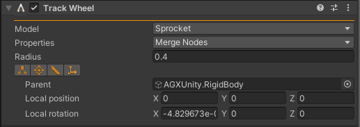
Track Wheel Inspector with initial estimated values.
In Reset of the Track Wheel component, the radius, model and the rotation axes
are estimated.
2.2.9.2. Setting up track friction
When setting up contact materials for tracks, it is often preferable to use oriented contact materials with lower friction orthogonal to the track plane to allow for turning. While this can be configured using a regular oriented Contact Material, the track model allows for automatic setting of the contact material orientation if the Track Friction Model option is enabled in the Friction Model.
When using this option, the X direction will be the main direction along the track travel direction and Y direction will be the orthogonal axis.
2.2.9.3. Track Rendering
By default, the Track component is not rendered. To render the track, the
AGXUnity.Rendering.TrackRenderer component is used. The Track renderer currently only supports
GameObject spawn based rendering.
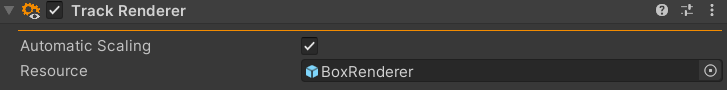
Track Renderer with default values.
The track renderer allows the user to specify a prefab which will be used to render each individual
node in the track. By default, this uses the Resources/Debug/BoxRenderer prefab to render
the nodes.
When the Automatic Scaling option is used, the selected rendering resource will be scaled based
on the track node size. This scaling assumes that the resource provided is sized a 1x1x1m node.
2.2.10. Tire
AGX Dynamics for Unity supports both One- and Two Body Tire models where One Body Tire is performing contact reduction and orienting the friction plane given the rotation axis. Two Body Tire is a model with two constrained rigid bodies, the tire and the rim, to model the deformation of the tire.
See AGX Dynamics Tire Model documentation for more information about Two Body Tire.
2.2.11. Wheel Joint
when modelling vehicles in AGX Dynamics for Unity, one common challenge is to model wheel movement accurately. The wheel joint component helps to achieve this by providing a specialized joint that allows for realistic wheel behavior, including three degrees of freedom: rotation around the axle, steering, and suspension movement.
The wheel joint models suspension using a lock controller which acts as a spring along the joint’s Z-axis while still allowing steering movement around the Z-axis and wheel rolling rotation around the Y-axis.
Note that while the wheel joint is essentially just another Constraint, there are some important points where it differs:
For other constraints the off-axes (Y & X) only serve to define the zero position of rotational constraints (or rotational violations for free frames). In contrast, the wheel joint uses the Y-axis to define the wheel rolling axis.
The wheel joint component comes with the translational §lock controller already enabled to provide suspension behavior.
For other constraints, flipping the attachment bodies will only change the sign of the constraint violations. For the wheel joint, however, the connected body is interpreted as the chassis while the reference body is treated as the wheel.
Please refer to the Constraint-section for more general information about constraint configuration in AGX Dynamics for Unity.
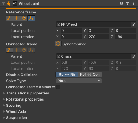
Wheel Joint Component in the Unity Editor
See AGX Dynamics Wheel Joint documentation for more information about the WheelJoint constraint.
2.2.12. Steering
For real vehicles, is is generally not acceptable to simply rotate both wheels by an equal amount when steering as this will cause the wheels to slip as they will be forced to be misaligned with the turning circle of the vehicle. To solve this, AGX Dynamics for Unity provides a Steering component that can be added which models various steering mechanisms that tries to align the wheels correctly based on a single input steering angle.
AGXUnity currently supports Ackermann, Bell-Crank, Rack-Pinion, and Davis steering mechanisms which each has their own way of calculating the correct steering angles for the left and right wheels based on the input steering angle and linkage geometry parameters as specified by the Steering Parameters.
The Steering component requires two Wheel Joint components to be assigned to it, one for each of the steered wheels. For the Steering component to function correctly, the wheel joints must have their steering axes (Z) aligned with each other and they must have the same connected parent rigid body (the vehicle chassis).
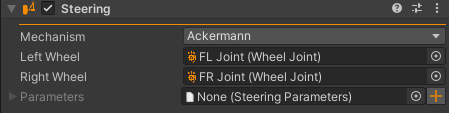
Steering Component in the Unity Editor
See AGX Dynamics Steering documentation for more information about the Steering models.
2.2.13. Hydro- and Aerodynamics
When an object is moving through air, water or another fluid it is affected by hydrodynamic effects such as lift, drag and added mass. This functionality is enabled by adding a Wind And Water Manager to the scene.
All objects interacting with the Water associated to the Wind And Water Manager will be subject to hydrodynamics forces. Aerodynamics is disabled by default and enabled using the Aerodynamics Parameters component.
See AGX Dynamics Hydro- and Aerodynamics documentation for more information.
Tip
Demo Scene example.
2.2.13.1. Hydrodynamics Parameters
It’s possible for objects to have different hydrodynamics specific parameters, such as drag, lift
and mesh resolution. Add the Hydrodynamics Parameters to the object, or group of objects,
the parameters should affect.
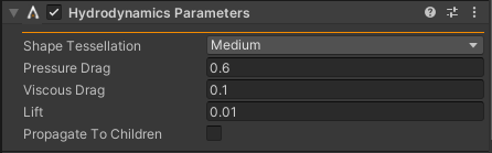
Hydrodynamics Parameters Inspector with default values.
Property |
Description |
Default |
|---|---|---|
Shape Tessellation |
Primitive shape types mesh tessellation quality: Low, Medium, High or Ultra High |
Medium |
Pressure Drag |
Pressure drag coefficient - affects force magnitudes along the surface normals. |
0.6 |
Viscous Drag |
Viscous drag coefficient - affects force magnitudes along the surface tangents. |
0.1 |
Lift |
Lift coefficient - affects force magnitudes along the surface normals depending on the tangential relative velocity. |
0.01 |
Propagate To Children |
Propagate Parameters to this object and all its children. |
false |
The parameter that controls the buoyancy force is Density in the Shape Material of the objects.
2.2.13.2. Aerodynamics Parameters
The Aerodynamics Parameters are identical to the Hydrodynamics Parameters. The only difference is that the aerodynamics calculations is disabled by default - resulting in an extra enabled flag in the Aerodynamics Parameters.
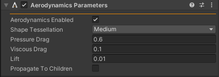
Aerodynamics Parameters Inspector with default values.
Note
Aerodynamics Enabled is by default true in this component, but any object not affected by Aerodynamics Parameters, Aerodynamics Enabled is implicitly false.
Capture showing that aerodynamics is disabled by default and how to enable it for a Rigid Body/Shapes, Wire and Cable.
2.2.14. Adaptive Model Order Reduction - AMOR
Adaptive Model Order Reduction, short AMOR, is a novel technique that reduces the computational complexity of a simulation by merging objects with each other, reducing the overall number of degrees of freedom in the simulation. Unlike sleep/wake, which many physics engines support, AMOR preserves the dynamics of merged sub-systems, enabling further interactions with other objects. This means that, e.g., parts of a coupled system (a complex crane for example) may be merged while the reactive forces on an active actuator is still accurate. Or having 1 500 rocks as payload on an operating Articulated Dump Truck, with complex wheel suspensions and hydraulic flatbed, the rocks may merge with the flatbed during operation, reducing the simulated system size with orders of magnitude.
See AGX Dynamics Merge Split Handler - AMOR documentation for detailed information about this functionality.
This feature is enabled by toggling Simulation (Manager) property Enable Merge Split Handler
to true/enabled and by enabling merge and/or split for objects using the Merge Split Properties
component.
Enabling the Merge Split Handler using the Simulation (Manager) instance in the scene.
Tip
Demo Scene example.
2.2.14.1. Merge Split Properties
The Merge Split Properties component controls enabling/disabling of merging and splitting
of objects, given Enable Merge Split Handler is enabled in the Simulation (Manager).
See AGX Dynamics AMOR Merge Split Properties documentation for further information about these properties.
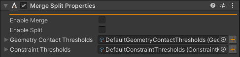
Merge Split Properties Inspector with default values.
Property |
Description |
Default |
|---|---|---|
Enable Merge |
Toggle if the object(s) may or may not merge with other objects. |
false |
Enable Split |
Toggle if the object(s) may or may not split from other objects. |
false |
Geometry Contact Thresholds |
Contact thresholds related to merging and splitting of objects in contact. |
Default |
Constraint Thresholds |
Constraint thresholds related to merging and splitting of constrained objects. |
Default |
Note
While the Merge Split Properties works with non-pager terrains, AMOR currently does not support splitting due to granule contacts. If this behaviour is desired, the bodies have to be manually split on particle impacts.
2.2.14.2. Manual merging of bodies
Sometimes, it might be advantageous to manually merge bodies without relying on the automatic merge conditions being met.
To achieve this, the KinematicLock component can be used. Any Rigid Body added to the KinematicLock
will be added to a single merged body, thus reducing the complexity of the model.
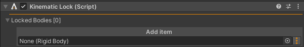
An empty KinematicLock component
2.2.15. Disable collisions
AGX Dynamics for Unity is using named collision groups to filter interactions between objects. Default interaction behavior is enabled, meaning collision groups defines groups that shouldn’t interact.
Objects supporting collision groups are:
2.2.15.1. Collision groups
List of collision groups that will be added to all supported components on subject game object. There’s a per group name option to propagate the group to children of this game object.
The collision groups aren’t affecting interactions until group pairs are disabled in the Collision Groups Manager.
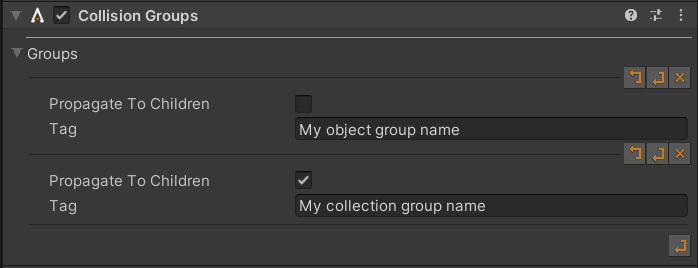
Collision groups Inspector with two groups added. My object group name will be added
to all supported objects on this game object. My collection group name will be added
to all supported objects on this game object and all its children.
Property |
Description |
Default |
|---|---|---|
Propagate To Children |
Toggle to share this group name with all children. |
false |
Force Contact Update |
For performance, the collision groups are by default only updated on impact or separation. When enabled, this forces updates of the collision groups for every contact event. |
false |
Tag |
Group tag/name. |
Note
Since AGX Dynamics supports groups for rigid bodies it’s not necessary to check
Propagate To Children for the rigid body groups to affect its shapes.
2.2.15.2. Collision groups for terrain particles
Since the terrain components include multiple “classes” of objects with the actual terrain heightmap being and the terrain particles being another, it is ambiguous which of these that the collisions group should be applied to. Since the heightfield is more akin to a regular geometry than the collection of particles, the collision group component, by design, only applies to that geometry.
If collision groups are required for the terrain particles it is possible to add the collision groups manually through scripting.
var terrainComponent = GetComponent<DeformableTerrainBase>().GetInitialized();
var soilSim = terrainComponent.GetSoilSimulationInterface();
soilSim.addCollisionGroup( "Particles".To32BitFnv1aHash() );
Note
The collisions group in the code example is added by hash to be compatible with Collision Groups Manager that also does this to the entries added.
2.2.16. Articulated Root
The Articulated Root component manages transform updates of Rigid Body instances when rigid bodies has other rigid bodies as parents. Any child Rigid Body of this component (in Hierarchy) will have its automatic transform updates disabled.
This component is suitable when, e.g., modeling of a robot, where the base may be considered root and fingers/tool the leafs. The rigid bodies affected by this component are collected using GetComponentsInChildren<AGXUnity.RigidBody>().
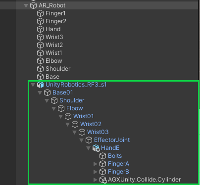
Hierarchy of robot where all objects within the green rectangle are Rigid Body instances constrained to each other with hinge or prismatic joints.
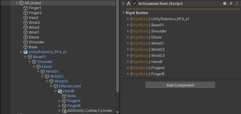
Articulated Root Inspector where AR_Robot contains the Articulated Root
component.
Tip
Articulated Robot example.
2.2.17. Rigid Body Emitter
The Rigid Body Emitter component is an emitter that emits Rigid Body instances given a set of prefab templates. A template is spawned inside a given shape sensor with a configurable distribution.
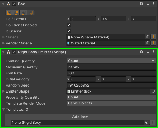
Rigid Body Emitter Inspector when the component has been added to a game object with a shape Box.
If the Rigid Body Emitter component is added to a game object containing a shape, the
Emitter Shape property is initialized with that shape. The Emitter Shape
property is required to be assigned but the Rigid Body Emitter doesn’t require a shape
component on its game object when the Emitter Shape may be assigned manually.
Property |
Description |
Default |
|---|---|---|
Emitting Quantity |
Unit quantity of given Emit Rate. The quantity can be: Count (default) - the number of instances created per second. Volume - the maximum volume emitted per second. Mass - the maximum mass emitted per second. |
Count |
Maximum Quantity |
The maximum quantity to emit. |
Infinity |
Emit Rate |
Quantity number (Emitting Quantity) per second. |
100 |
Initial Velocity |
Reference initial velocity of an emitted body, given in the frame of the Emitter Shape. This velocity is slightly randomized when a body is emitted. |
(0, 0, 0) |
Random Seed |
Random seed used when emitting bodies which are randomly positioned within the emitter shape and receives some randomized velocity with respect to the given initial velocity. The seed is randomized during component Reset (i.e., when the component is added to a game object or when Reset is pressed from the component context menu). |
Random during Reset |
Emitter Shape |
Sensor shape the bodies should be emitted from within. |
null |
Probability Quantity |
The probability quantity of the templates probability weights. |
Count |
Template Render Mode |
Whether to spawn Game Objects or render Instanced Mesh when rendering the emitted bodies |
Game Objects |
Templates |
List of added template prefabs. The Probability Weight of a template is revealed when the list is expanded. See figure below. |
Empty |
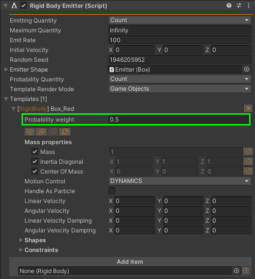
A template prefab expanded in the Inspector has an extra property - Probability Weight. The Probability Weight is controlling how likely it is that this specific template is spawned.
2.2.17.1. Emitter Templates
An emitter template is a rigid body prefab of any shape and/or visual structure as children. The name of the template has to be unique to the Rigid Body Emitter because AGX Dynamics is emitting bodies with a callback and the name of the emitted body is mapped to the prefab resource in Unity.
Note
If the Instanced Mesh render option is selected on the emitter, ensure that the visual material assigned to the template supports instancing.
To add the template to the emitter, drag and drop the prefab from the project view to the Add item
area or click the context icon ![]() on the right for a list of valid prefabs that
can be added.
on the right for a list of valid prefabs that
can be added.
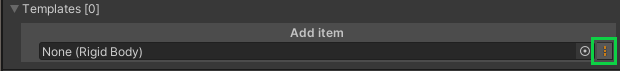
Note
The context icon marked in the image above is only searching for supported prefabs in folders with
a Resources folder as a parent. E.g., Assets/Resources/MyTemplates/thisTemplate.asset
will show up there. Still, it’s not required for a template to be located in a resources folder.
2.2.17.2. Sink
A rigid body emitter sink is a shape where given, or all, emitted instances from one or many Rigid Body Emitter disappears when in contact with the shape. As soon as the contact between a sink shape and an emitted rigid body is registered, the rigid body is removed from the simulation and its visual representation is destroyed.
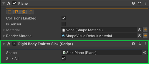
Default Rigid Body Emitter Sink Inspector when added to a game object with a shape (Plane). Any shape type is supported to be a sink.
Property |
Description |
Default |
|---|---|---|
Shape |
The sink shape instance. |
null |
Sink All |
Sink all emitted rigid bodies, independent of template or Rigid Body Emitter instance. |
true |
Sink Templates |
Visible in the Inspector when Sink All is false. List of Emitter Templates this sink should destroy. The template rigid body may be part of any Rigid Body Emitter. |
empty |
Example showing Sink All and the granularity of using Sink Templates in different sinks.
2.2.17.3. AMOR on emitted bodies
When using a Rigid Body Emitter the amount of bodies in the simulation can easily grow to large numbers. To achieve better performance it is advantageous to use Adaptive Model Order Reduction - AMOR to reduce the computational complexity of the simulation. To accomplish this, the Merge Split Properties component should be added to the Rigid Body Emitter GameObject.
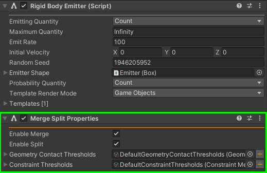
Merge Split Properties applied to the Rigid Body Emitter.
2.2.18. Plotting and data acquisition
To create plots in AGXUnity, the Plot Component can be used together with one or several Data Series that hold the plot data.
The Plot Component can also be used to write data to a (.csv) file on disk for later analysis. Plotting can be done in either Visual Scripting or
C# scripting.
Note
Use the Unity Package Manager to install the Visual Scripting package, if not already installed
2.2.18.1. Prerequisite setup for plotting with Visual Scripting
Add
AGXUnitytoEdit -> Project Settings -> Visual Scripting -> Node Libraryand then press theRegenerate Nodesbutton.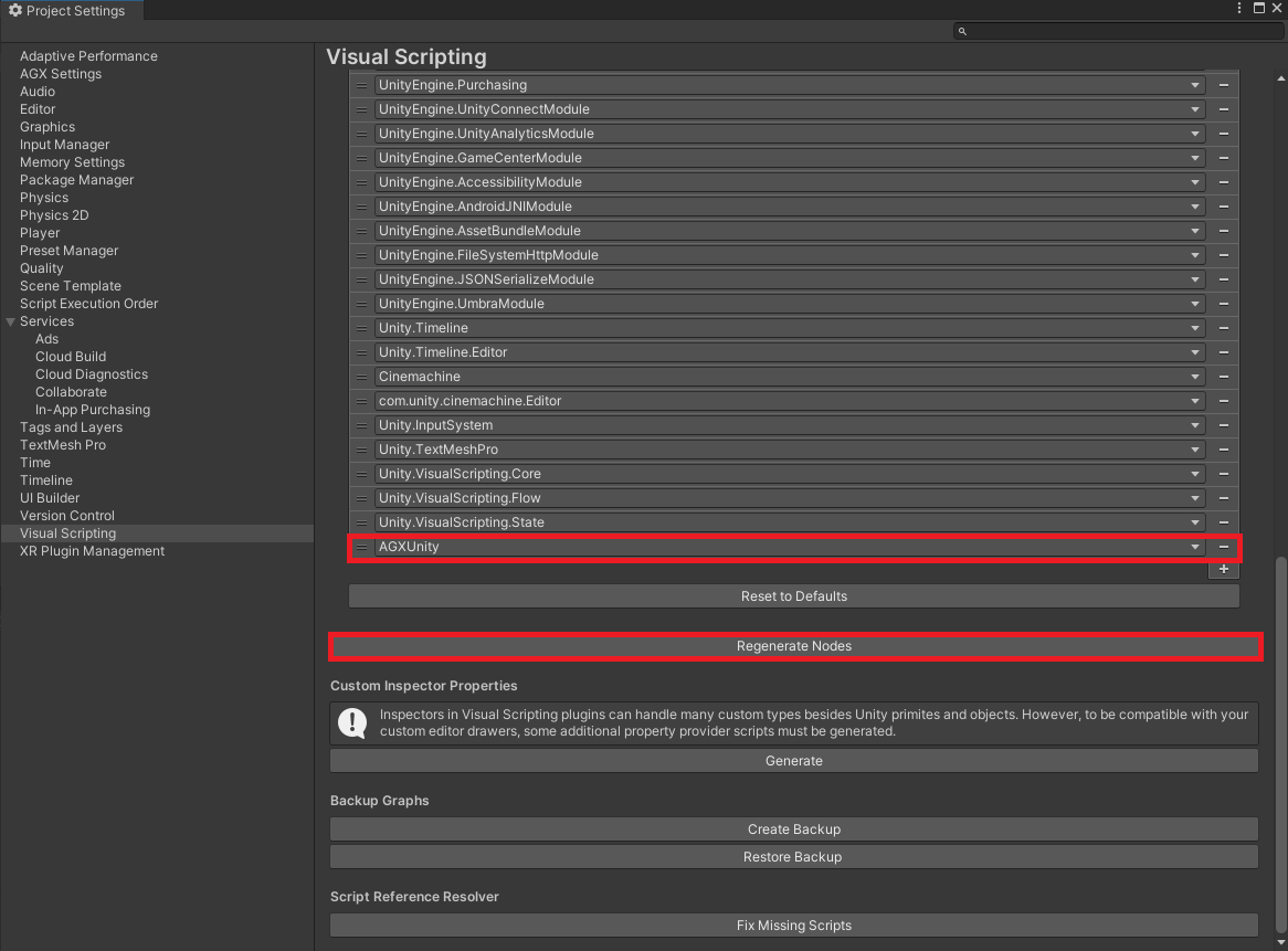
2. Add Plot and DataSeries from AGXUnity.Utils to Edit -> Project Settings -> Visual Scripting -> Type Options.
You will most likely want to add RigidBody from AGXUnity as well. This example will also assume you have done so. Then press Regenerate Nodes again.

2.2.18.2. Creating a plot in Visual Scripting
Create a new empty game object and add a
Plot Componentto a game object.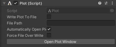
Add one or several
Data Seriesto the same game object you created in step 1 and set a meaningful name.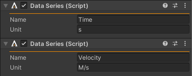
Add a
Script Machineto the same game object you created in step 1.Add variables of the type
Data Seriesto theScript Machine. Drag theData Seriescomponents in the game object into the value fields of theData Seriesvariables in theScript Machine.
5. In the Visual Script, create a plot by calling the Create Plot function from the Plot Component from the On Start event. Connect your Data Series variables to the X Series and Y Series input ports axis respectively.
There are two Create Plot functions, one is for the Visual Scripting which takes Data Series as argument.
The other one is for plotting in C# scripts, and expects agxPlot.DataSeries as input. Make sure to pick the correct one.
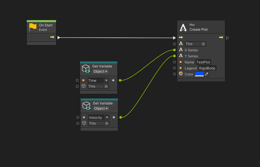
6. Write data to your Data Series during Simulation by calling the Write function from the On Update event.
Below is an example where we plot the linear velocity on the y-axis of a rigid body. This will require a scene variable of our rigid body to call Get Linear Velocity on.
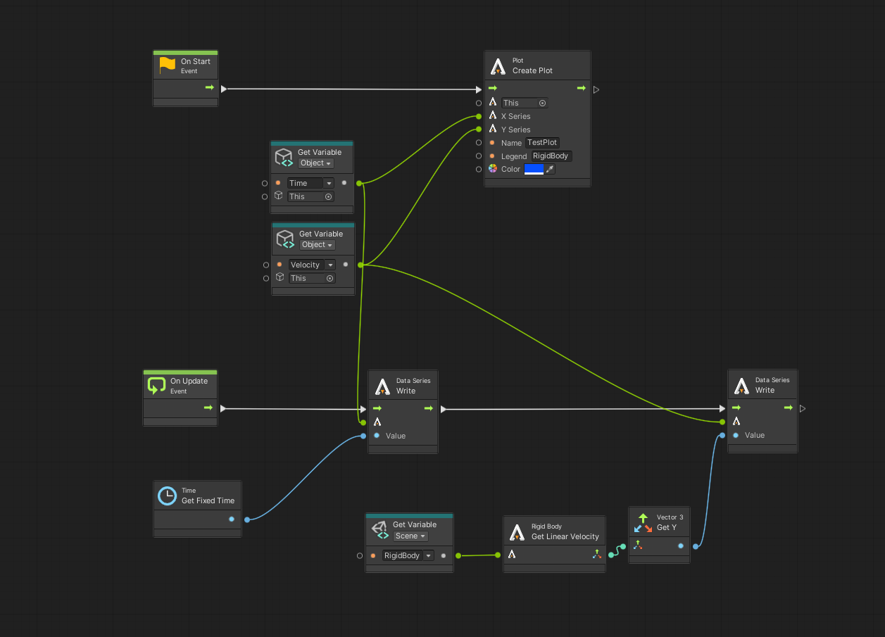
By default, the plot window is not automatically opened in your default browser on Play.
This behavior can be controlled through the Auto Open Plot Window property in the Plot Component details Panel.
7. To plot multiple curves on the same plot, simply call the Create Plot function again with the desired Data Series. Remember if you add any new Data Series you will need to write values to the new Data Series on update as well.
If you want to plot curves on different plots, the Name parameter in the Create Plot function should be different from the Name parameter in a previous Create Plot function.
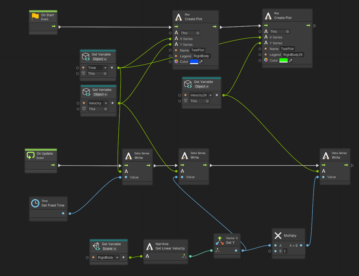
2.2.18.3. Quickly create required objects for plotting
By clicking on the menu item Plot in AGXUnity -> Plot a GameObject called PlotObject will be created with an added Plot component,
two added DataSeries components and a Script Machine. A basic TemplatePlot.Asset will also be created and put into the Assets folder. Now we just need to initialize all variables and connect the nodes in the Visual Script to get a working plot.
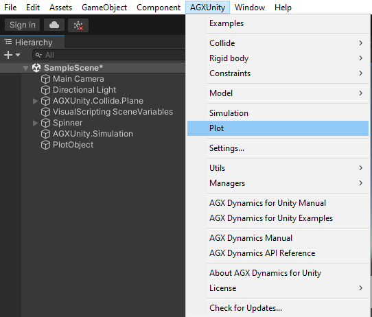
2.2.18.4. Creating a plot in a C# script
Create a new empty game object and add a
Plot Componentto a game object.
Create a new
C#script and add it to the same game object you created in step 1.Example of a minimal working example.
using UnityEngine;
using AGXUnity;

public class ScriptPlot : ScriptComponent
{
  // A GameObject we want to plot some property of
  public GameObject GameObject;

  // Two classes to hold data for the properties we want to plot
  private agxPlot.DataSeries x;
  private agxPlot.DataSeries y;

  // Start is called before the first frame update
  protected override bool Initialize()
  {
    // Get the plot component in our game object
    AGXUnity.Utils.Plot plot = GetComponent<AGXUnity.Utils.Plot>().GetInitialized<AGXUnity.Utils.Plot>();

    // Initialize our x- and y-axis
    x = new agxPlot.DataSeries("Time");
    y = new agxPlot.DataSeries("Velocity");

    // Set units for what we want to plot
    x.setUnit("s");
    y.setUnit("M/s");

    // Create a plot with our x- and y-axis with a plot name and legend
    plot.CreatePlot(x, y, "ScriptPlot", "RigidBody", new Color(1, 0, 0));

    return true;
  }

  // Update is called once per frame
  void Update()
  {
    // Push data every update to our x- and y-axis
    x.push(GetSimulation().getTimeStamp());
    y.push(GameObject.GetComponent<AGXUnity.RigidBody>().Native.getVelocity().y);
  }
}
2.2.18.5. Writing data to file
The Plot Component can automatically write data to a (.csv) file on disk.
This is controlled through the Write To File property in the Plot Component panel.
If set to true, a file with the name given by the File Output Name will be created. The root path is in the project folder Assets. Default behaviour of writing to file is
to not overwrite any existing files. If we want to overwrite a file we need to set the Force File Overwrite property to true.
2.2.19. Sensors
AGX enables simulation of a variety of sensor types within AGXUnity. This section describes the process of setting up sensor simulation within AGXUnity and the supported sensor types available.
2.2.19.1. Sensor Environment
To keep track of which objects in the scene that is visible to extrospective sensors, such as LiDAR
sensors, the SensorEnvironment manager class is used. If an object is not in the sensor environment
it is as if the object is not present in the scene from the point of view of the sensors. The configuration
of the objects in the sensor environment depends on what sensors are used and will be described further
under the respective sections for the relevant sensors.
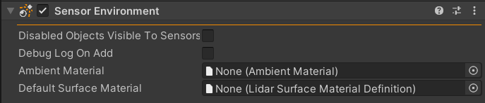
SensorEnvironment Inspector with default values.
Property |
Description |
Default |
|---|---|---|
Disabled Objects Visible To Sensors |
When enabled, all objects are added to the sensor simulation, regardless of whether they are enabled in the scene or not. |
false |
Debug Log On Add |
Prints an info message to the console whenever an object is added to the sensor simulation when enabled. |
false |
Magnetic Field |
Used for magnetometer sensor. The types are None, Uniform and Dipole. The field is defined by zero to two vectors depending on the mode. |
Uniform |
Included Layers |
Specifies the GameObject layers which objects have to be on to be included in the sensor simulation |
Everything |
Ambient Material |
The Lidar Ambient Materials to use in the sensor simulation to simulate atmospheric interference. |
null |
Default Surface Material |
The Lidar Surface Material Definition to apply to objects that do not have an explicit Lidar Surface Material |
null |
Note
Adding a SensorEnvironment (or using a sensor component that requires it) causes the Simulation (Manager)
PreIntegratePositions property to be set to true.
2.2.19.1.1. Adding objects to the Sensor Environment
To enable as seamless use of sensor simulation as possible, all AGXUnity components are added to the sensor
simulation as well as all MeshFilter components are added to the environment at initialization.
Subsequently added objects with AGXUnity components are automatically added to the sensor environment as well.
Due to limitations in Unity, this is not true for plain Unity objects with MeshFilters. The reason for this is
that Unity does not provide an efficient way of querying for newly added objects and as such, the sensor
environment has no way of knowing when new MeshFilters are added to the scene. To mitigate this issue there are
two options:
- If a prefab is being instantiated, add any script that derives from AGXUnity.ScriptComponent to the root object.
- Manually call SensorEnvironment.Instance.RegisterCreatedObject( newlyCreated ) to register the newly added object.
2.2.19.1.2. Fine grained control of which objects are added to the Sensor Environment
While adding all parts of the scene by default is fine for smaller simulations, it is sometimes necessary to
control which parts of the simulation are added to the sensor environment with a higher resolution.
The ExplicitSensorEnvironmentInclusion component is meant to provide this fine grained control
by explicitly exclude (or include) a subtree in the GameObject hierarchy.
Property |
Description |
Default |
|---|---|---|
Include |
Whether or not the affected subtree should be included in the sensor environment |
true |
Propagate To Children Recursively |
Whether to apply this object’s inclusion rule to child objects as well |
true |
It is also possible to specify in the Sensor Environment inspector which Unity GameObject layers should be included in the simulation.
Warning
While the ExplicitSensorEnvironmentInclusion component supports runtime changes to, for example, toggle the
inclusion state of an object, GameObject modifications such as moving objects in the hierarchy or changing layers after
they’ve been added to the SensorEnvironment are generally not supported. The exception to this rule is adding objects
for the first time as described in Adding objects to the Sensor Environment.
2.2.19.2. Simulating LiDAR sensors
AGXUnity support GPU accelerated LiDAR sensor simulation. This module utilizes raytracing to accurately simulate LiDAR rays along with atmospheric, surface, and sensor distortions. For objects to be visible to the LiDAR sensor they have to be added to the Sensor Environment.
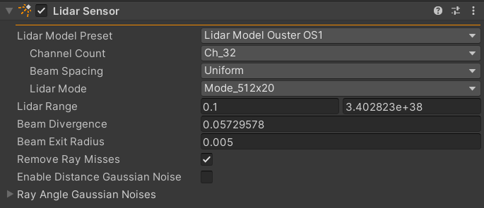
LiDAR inspector with default values.
Property |
Description |
Default |
|---|---|---|
Lidar model Preset |
The preset model to use for the LiDAR sensor, this choice impacts what parameters are visible in the LidarSensor inspector. See LiDAR Preset models for more information. |
Ouster OS1 |
Remove Ray Misses |
Whether or not to remove output points representing rays that missed all objects in the scene. |
true |
Enable Distance Gaussian Noise |
When enabled, noise is added to the output distance of points given a specified gaussian distribution. |
false |
Ray Angle Gaussian Noises |
A list of gaussian angle noises that, when enabled, are applied to the rays shot from the LiDAR sensor. |
false |
Note
Rotating LiDAR’s generally rotate around the local Z-axis and for compatibility reasons.
Tip
Demo Scene and Auto-brake using LiDAR examples.
2.2.19.2.1. Prerequisites
The main requirement for running LiDAR simulation in AGXUnity is having a CUDA enabled GPU and running AGXUnity in an environment where CUDA and Optix libraries are properly setup. This means that currently, only NVidia cards are supported.
Under normal conditions it is sufficient to install the drivers for a machine’s GPU to install all the required libraries to the system. However, in containerized environments, the relevant GPU resources also has to be exposed to the running container alongside any required system libraries.
For Docker containers it should suffice to install and configure the NVIDIA Container Toolkit as per the documentation
For WSL systems, the process is a bit more involved. As of writing, the official NVIDIA driver support for WSL does not include Optix support. The best workaround that was found while writing this documentation was following the steps outlined in this github comment. - Based on install instructions from another library Mitsuba - Thread about the issue on NVIDIA’s forums
If you require further help setting up your environment to support LiDAR simulation. Please contact us at support@algoryx.com and describe your system setup.
2.2.19.2.2. LiDAR Preset models
The LiDAR sensor contains some preset models used to easily configure the LiDAR to behave like a specific LiDAR model. These preset models might require different sets of parameters to configure depending on the specific model preset used. These preset models and their respective parameters are outlined in this section. More models will be added on request, if a model required for a specific simulation is missing, send a request at support@algoryx.com with information about the LiDAR model.
2.2.19.2.2.1. Ouster OS 0, 1, & 2
The Ouster OS models come in three varieties:
The OS 0 - Ultra-Wide View High-Resolution Imaging Lidar (OS0 Datasheet)
The OS 1 - Mid-Range High-Resolution Imaging Lidar (OS1 Datasheet)
The OS 2 - Long-Range High-Resolution Imaging Lidar (OS2 Datasheet)
These lidar models come with three independently configurable settings that they share:
Setting |
Description |
Default |
|---|---|---|
Channel Count |
The amount of channels, or vertical resolution, of the LiDAR. |
32 |
Beam Spacing |
The spacing of the beams shot by the LiDAR |
Uniform |
Lidar Mode |
The mode of operation of the LiDAR. This configures both the resolution and the frequency of the LiDAR as specified by the datasheets |
512 pts x 20Hz |
2.2.19.2.2.2. Generic Horizontal Sweep
The Generic Horizontal Sweep model allows specifying a generic LiDAR that continuously sweeps horizontally over a given horizontal FoV while capturing points in a provided vertical FoV. The rays shot by the LiDAR is equally spaced and have a specified horizontal and vertical angle difference between them.
Setting |
Description |
Default |
|---|---|---|
Frequency |
The frequency of a complete LiDAR sweep |
10Hz |
FoV Mode |
Specifies whether the FoV should be centered around the lidar forward or provided as a window |
Centered |
Horizontal/Vertical FoV |
The field of view of the LiDAR sweep, in degrees. Only used when the FoV Mode is set to Centered |
360° x 35° |
Horizontal/Vertical FoV Window |
The field of view of the LiDAR sweep, in degrees, Only used when the FoV Mode is set to Window |
[-180°,180°] x [-17.5°,17.5°] |
Resolution Mode |
Specifies which property of spacing and total point count is specified by the resolution, the other one will be calculated based on the window |
Degrees Per Point |
Horizontal/Vertical Resolution |
The angle between neighboring LiDAR rays, in degrees. Only used when the Resolution Mode is set to Degrees Per Point |
0.5° x 0.5° |
Horizontal/Vertical Resolution Total |
The total amount of points in the given direction. Only used when the Resolution Mode is set to Total Points |
1024 x 256 |
Range |
The range of the lidar rays outside of which ray intersections will be counted as misses |
[0.1f,float.MaxValue] |
Beam Divergence |
Divergence of the lidar laser light beam [deg]. This the total ‘cone angle’, i.e. the angle between a perfectly parallel beam of the same exit dimater to the cone surface is half this angle. This property affects the calculated intensity. |
0.0573° |
Beam Exit Radius |
The diameter of the lidar laser light beam as it exits the lidar [m]. This property affects the calculated intensity. |
0.005 |
2.2.19.2.2.3. Livox Models
The Livox lidar models are simulated using a repeating but large set of ray angles, coming close to the non-repeating pattern displayed by the Livox hardware lidars. The only configuration option available is the Downsample option, which skips ray angles in the pattern in order to get the same shape but less points per second. The list of available models are:
Livox Avia is a mid-range 70 by 77 degree fov lidar with non-repeating pattern.
Livox HAP is a mid-range 120 by 25 degree fov lidar with non-repeating pattern for automotive applications.
Livox Horizon is a mid-to-long-range 82 by 25 degree fov lidar with non-repeating pattern.
Livox Mid40 is a short-to-mid-range circular 38 degree fov lidar with non-repeating pattern.
Livox Mid70 is a short-to-mid-range circular 70 degree fov lidar with non-repeating pattern.
Livox Mid360 is a short range 360 by 59 degree fov lidar with non-repeating pattern.
Livox Tele is a long range 14 by 16 degree fov lidar with non-repeating pattern.
The ray pattern files are sampled from the Livox Sensor SDK and then included with this package compressed to binary. The ray pattern files are released by Livox under MIT license. These same files are under the same license in this module.
2.2.19.2.2.4. Read Pattern From File
A lidar reading ray patterns from a file can be set up using a custom file and values. Instantiate the LidarModelReadFromFile class and define file path and optionally the following parameters:
frequency - Lidar frame frequency (Hz).
frameSize - Number of samples per lidar frame.
downsample - Optionally reduces the number of samples by dividing with this integer.
path - Absolute or relative file path, if filetype != “.csv” the rest of the parameters are ignored.
twoColumns - If true, file has only azimuth,elevation (no first column).
anglesInDegrees - If true, angles are in degrees, else radians.
firstLineIsHeader - If true, ignore first line.
Delimiter - CSV delimiter character.
2.2.19.2.3. Setting surface material
Surface materials are setup as additional components on the GameObjects in the scene. To specify a surface material for any component,
ScriptComponent or MeshFilter, add a LidarSurfaceMaterial component to the GameObject.
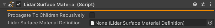
LidarSurfaceMaterial inspector with default values.
Property |
Description |
Default |
|---|---|---|
propagate To Children Recursively |
When enabled, the provided Lidar Surface Material Definition is applied to all children of this object as well. |
false |
Lidar Surface Material Definition |
The Lidar Surface Material Definition to apply to this object. |
null |
This component does not include many options itself but rather acts as a container for specifying a Lidar Surface Material Definition asset. When this component is added to an object it specifies to the Sensor Environment that the provided material definition should be used for the attached components that are added to the sensor simulation, and optionally to any such components in child objects of the component.
When resolving the surface material to use for a given component, the closest instance that would be applied
to a given component is chosen. That means that if a component has multiple LidarSurfaceMaterial components
in it’s parents, the closest one with the option to propagate to children is picked, or if present, the one on the
GameObject itself is chosen.
2.2.19.2.4. Setting ambient material
As important as how the LiDAR rays interact with surfaces in the simulation, is how they interact with the medium through which they travel through. In AGXUnity, this is configured by providing an Lidar Ambient Materials to the Sensor Environment. This allows the simulation to simulate non-ideal conditions in which there might be inaccuracies due to lower visibility from the LiDAR sensor’s point of view. Please refer to the Lidar Ambient Materials section for more information on configuring various atmospheric phenomena.
2.2.19.2.5. Rendering output points
To render the output points of a LiDAR sensor, AGXUnity provides a Lidar Point Cloud Renderer component that can be attached to the GameObject with the Lidar Sensor component. This component adds an output to the sensor and renders the points with a specified color based on the return intensity of the point.
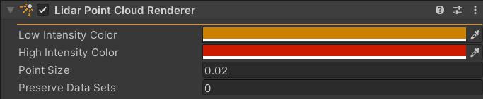
LidarPointCloudRenderer inspector with default values.
Property |
Description |
Default |
|---|---|---|
Low/High Intensity Color |
The color interval used to render the intensity of the output points. |
Orange/Red |
Point Size |
The absolute size at which to render the points |
0.2 |
Preserve Data Sets |
By default, only the last frame’s output points are rendered, setting this allows for the last n+1 frames to be rendered instead, where n is the value of this property. |
0 |
2.2.19.2.6. Generic output handling
Most likely, simply rendering the points is not useful to the simulation in and of itself. To handle outputs from a Lidar Sensor component generically, the following steps need to be taken in a script:
Create an
AGXUnity.Sensor.LidarOutputwith the required agxSensor.RtOutput.Field.Add the created
LidarOutputto the Lidar sensor component.Create a struct to hold the output data of the
LidarOutput. Note that this struct has to have the same size and layout as the specified fields. If any errors occur related to the size of the output, try adding padding to the fields or output struct, or specifying an explicit memory layout to the struct using the C# System.Runtime.InteropServices.StructLayoutAttribute.Fetch the data into an array of your output struct using the
LidarOutput.View<>method with the output struct as the type parameter.
Putting it together, here is an example snippet of how data is fetched for the Lidar Point Cloud Renderer component:
using AGXUnity;
using AGXUnity.Sensor;

public class GenericOutputHandler : ScriptComponent
{
   private LidarOutput m_pointOutput;

   // 3. Create output struct
   private struct PosIntensityOutput
   {
      public agx.Vec3f xyz;   // XYZ_VEC3_F32
      public float intensity; // INTENSITY_F32
   }

   protected override bool Initialize()
   {
      // 1. Create LidarOutput
      m_pointOutput = new LidarOutput
      {
         agxSensor.RtOutput.Field.XYZ_VEC3_F32,
         agxSensor.RtOutput.Field.INTENSITY_F32
      };

      // 2. Add LidarOutput to LidarSensor.
      LidarSensor lidar = GetComponent<LidarSensor>();
      lidar.GetInitialized().Add(m_pointOutput);

      Simulation.Instance.StepCallbacks.PostStepForward += HandleOutput;

      return true;
   }

   private void HandleOutput()
   {
      // 4. Fetch data
      PosIntensityOutput[] data = m_pointOutput.View<PosIntensityOutput>(out uint count);

      // Use data...
   }
}
2.2.19.2.7. Publishing LiDAR data over ROS2
it is often useful to be able to access LiDAR data over ROS2 for interaction with other applications.
To enable this, AGXUnity provides a LidarROS2Publisher component that can be added to sensor
objects.
This component publishes ROS2 PointCloud2 messages on up to three three topics. Each topic specifies a set of point fields that is published as part of the pointcloud:
PCL24 is a 24 byte-per-point pointcloud format that includes the following fields:
XYZ Position 3 x 32 bit floats
Padding 32 bits
Intensity 32 bit float
Ring ID 16 bit uint
Padding 16 bits
PCL48 is a 48 byte-per-point pointcloud format that includes the following fields:
XYZ Position 3 x 32 bit floats
Padding 32 bits
Intensity 32 bit float
Ring ID 16 bit uint
Padding 16 bits
Azimuth 32 bit float
Distance 32 bit float
Return Type 8 bit uint
Padding 46 bits
Timestamp 64 bit float
InstanceID is a 20 byte-per-point with very minimal data that includes the following fields:
Position XYZ 3 x 32 bit floats
Entity ID 32 bit int
Intensity 32 bit float
2.2.19.3. Simulating IMU Sensors
Inertial Measurement Units (IMUs) can appear in multiple different configurations, both of sub-sensors and output formatting, depending on manufacturer and requirement specifications. Using the IMU Sensor Component, an IMU can be set up quickly with configurable sensor modules and output. The available modules are Accelerometer, Magnetometer and Gyroscope.
The IMU sensor attaches to a rigid body, allowing access to acceleration and other data from the physics system. The ImuSensor Component will track the closest parent object with an AGX RigidBody component.
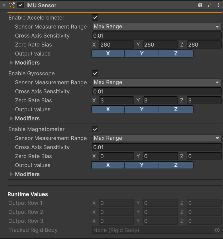
IMU Sensor component with default values.
Property |
Description |
Default |
|---|---|---|
Enable [module name] |
If enabled, activate module. |
true |
Sensor Measurement Range |
The range of values the sensor can measure. Values outside the range will be truncated. The range can be set to max float range, the same for all three axis, or different per axis. Unit is the same as all length measurements in the simulation, meters by default. |
Max float range |
Cross axis sensitivity |
A typical sensor has some error where readings on one axis will affect the others. This value represents this error. It is expressed as a ratio. |
0.01 |
Zero rate bias |
The value when there is no reading from the sensor nor any noise / modifiers applied. |
[0, 0, 0] |
Output values |
Which axes to include in the simulation output. |
X Y Z |
Modifiers |
See output modifier section below. |
Note
For convenience reasons, each IMU sensor Component allows for one or zero of each module. If a sensor with, say, two accelerometers is needed, it is possible to create one through C# scripts using the ImuSensor component as an example. The limit from C# is three modules in total.
2.2.19.3.1. Accelerometer module
The accelerometer provides a standardized way to measure accelerations applied to a rigid body, with up to three degrees of freedom. Measurement range, signal scaling and signal noise is configurable to comply with any desired module specification.
2.2.19.3.2. Gyroscope module
The gyroscope provides a standardized way to measure the rotation experienced by a rigid body, with up to three degrees of freedom. Measurement range, signal scaling and signal noise is configurable as with the other modules. Additionally, for a gyroscope module, linear acceleration effects are configurable.
2.2.19.3.3. Magnetometer module
The magnetometer provides a standardized way to measure the magnetic field experienced by a rigid body, with up to three degrees of freedom. Measurement range, signal scaling and signal noise is configurable as with the other modules.
The magnetic field is defined in the Sensor Environment Component. The module will measure the field strength and orientation using the IMU frame orientation and position as a reference.
2.2.19.3.4. Output modifiers
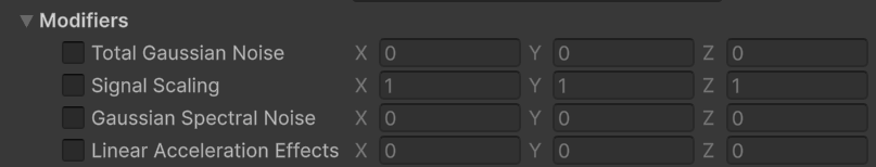
Optional value modifiers of the sensor module output.
Property |
Description |
Default |
|---|---|---|
Total Gaussian Noise |
Base level noise in the measurement signal, per axis, RMS. |
0, 0, 0 |
Signal Scaling |
Per-axis scaling of the signal. Useful when the sensor should output non-SI units. |
1, 1, 1 |
Gaussian Spectral Noise |
Frequency dependendent noise, per axis, RMS. |
0, 0, 0 |
Linear Accelaration Effects |
Gyroscope only - perturbations based on linear accelaration, per axis. |
0, 0, 0 |
2.2.19.4. Simulating Encoder Sensors
This sensor provides a standardized way of measuring an unconstrained degree of freedom of a constraint, acting both as a linear or rotary encoder. Compatible constraints are:
Hinge
Prismatic
Cylindrical joint
Wheel Joint
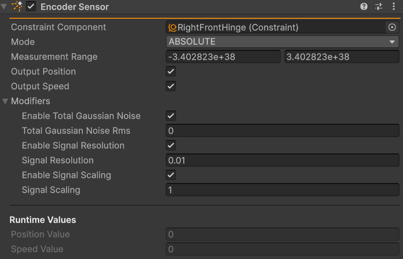
Encoder Sensor Component in the Inspector
Property |
Description |
Default |
|---|---|---|
Constraint Component |
The tracked GameObject. Will refer to the first compatible Component on the object. |
- |
Mode |
Incremental or absolute measuring of position. Note - when using incremental, set a suitable measurement range! |
Absolute |
Measurement Range |
Measurement range - values outside the range will be truncated. |
0, 0, 0 |
Sample Wheel Joint |
Only visible when Wheel Joint selected - What Wheel Joint DoF to measure |
Wheel Axle |
Sample Two Dof |
Only visible when Cylindrical Joint selected - Which of the two free DoFs to sample |
First |
Output Position / Speed |
What output will be written to the buffer. |
Position |
Total Gaussian Noise |
RMS of noise added to the signal. |
Disabled, 0 |
Signal Resolution |
Signal measurement step size. |
Disabled, 0.001 |
Signal Scaling |
Scaling of signal, useful if non-SI unit output is desired. |
Disabled, 1 |
2.2.19.5. Simulating Odometer Sensors
This sensor provides a wheel-rotation based odometer, measuring the distance traveled due to the rotation of a constraint.
Hinge
Cylindrical joint
Wheel Joint
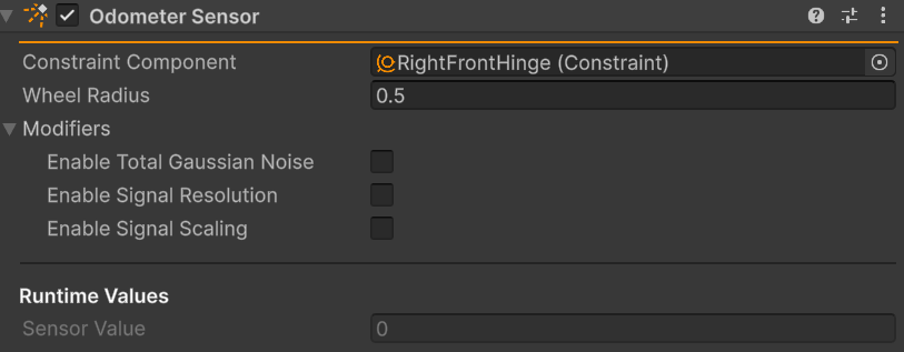
Odometer Sensor Component in the Inspector
Property |
Description |
Default |
|---|---|---|
Constraint Component |
The tracked GameObject. Will refer to the first compatible Component on the object. |
- |
Wheel Radius |
Radius of the wheel whose travel is being measured |
0.5 |
Total Gaussian Noise |
RMS of noise added to the signal. |
Disabled, 0 |
Signal Resolution |
Pulses per wheel resolution (the inverse of signal resolution). |
Disabled, 1024 |
Signal Scaling |
Scaling of signal, useful if non-SI unit output is desired. |
Disabled, 1 |
2.2.20. High Level Components
While most of the components have a direct mapping to an underlying AGX type, some components instead combine multiple components into a higher level aggregate component. These components provide an example of how more complex systems could be modeled using the base components available.
2.2.20.1. Gear Constraint
The GearConstraint component models a geared coupling between two constraint
using an underlying powerline
system. Specifically, any translational constraints are added as actuators to the
powerline system and translational motion is converted to rotational motion. After
any potential conversion, the rotational motion of each end of the system is constrained
by a powerline gear configured by the ratio specified in the component.
This is an example of a simple powerline where no added power source is required.
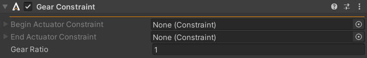
Gear Constraint inspector with default values.
2.2.20.2. Wheel Loader Components
An example of a more complex powerline can be seen in the WheelLoader,
WheelLoaderInputController, and WheelLoaderBucketTiltController
components. These components model various different aspects of a wheel loader.
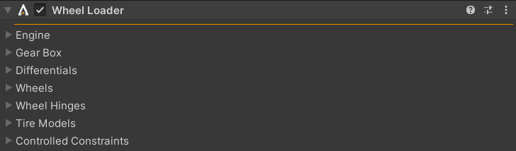
Wheel Loader inspector with default values.
The WheelLoader component is an abstraction around a generic wheel loader powerline
which builds a powerline with an engine, torque converter, gearbox, front back and center differentials and four tires.
Additionally this component wraps the central steering hinge and the bucket prismatic constraints.
Each component of the wheel loader is found by name so it is important that the various components in the model are named appropriately:
The steering hinge should be named WaistHinge
The prismatic constraints which elevate the bucket should be named LeftLowerPrismatic and RightLowerPrismatic respectively.
The bucket tilt prismatic constraint should be name CenterPrismatic
The wheel bodies should be divided into Wheel and Rim and be prefixed with Right/Left and Front/Rear. e.g RightRearWheel and LeftFrontRim. There should be a total of 8 bodies for the wheels.
Each wheel should have a hinge called Right/Left, Front/Rear, Hinge. e.g. LeftRearHinge
Each wheel should have a lock joint connecting the wheel and rim components, name does not matter here.
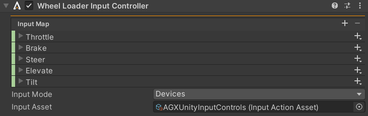
Wheel Loader Input Controller with default values.
The WheelLoaderInputController connects a Unity Input System Action Map to the previously described
WheelLoader component. The asset provided should contain an action map with the following actions defined:
Throttle
Brake
Steer
Elevate
Tilt
The WheelLoaderBucketTiltController is meant to compensate for changes in bucket tilt
caused by changes in bucket elevation. The component tries to keep the bucket level as the elevation
changes.
For an example of how to use the wheel loader components see the Wheel Loader on Terrain example.
2.2.20.3. Conveyor Belt
The ConveyorBelt component models a tracked conveyor belt using a set of parallel Track components
connected by lock joints at various points.
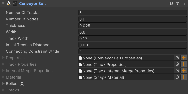
Conveyor Belt inspector with default values.
Most of the properties available in the ConveyorBelt component are the same as the corresponding
properties in the Track component. Additionally, the properties include options to control the number
of tracks to use to simulate the conveyor belt, their widths, as well as the stride, in nodes, between the
constraints connecting the individual tracks to each other.
2.3. Managers
2.3.1. Simulation (Manager)
The Simulation is the fundamental single instance scene object of AGX Dynamics for Unity. Simulation owns almost all AGX Dynamics for Unity instances in a scene.
Empty scene vs. scene with an AGX Dynamics for Unity instance vs. explicitly added Simulation (disabling gravity).
To add Simulation to a scene, click AGXUnity -> Simulation from the
main menu.
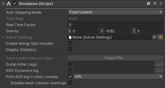
Simulation Inspector with default values and various features to dump the simulation to AGX Dynamics native formats.
Property |
Description |
Default |
|---|---|---|
Auto Stepping Mode |
Simulation Stepping Mode: Fixed Update, Update or Disabled |
Fixed Update |
Time Step |
Simulation time step size. |
0.02 (Unity) |
Fixed Update Real Time Factor |
When Auto Stepping Mode is Fixed Update and Maximum Allowed Timestep > Fixed Timestep in the project settings, this factor can be used to skip simulation updates when Unity is catching up on lost time. If 0.0 (disabled), the simulation time will match Unity fixedTime. If 0.333, three times (1.0/0.333) Fixed Timestep may be spent in stepping the simulation before additional simulation steps are skipped. See recommended settings in Stepping Mode. |
0.0 (disabled) |
Gravity |
Gravity acceleration in the simulation. |
(0, -9.82, 0) |
Solver Settings |
Solver Settings of the simulation. |
null |
Pre Integrate Positions |
Set true to integrate positions at the start of the timestep rather than at the end. |
false |
Enable Merge Split Handler |
false |
|
Display Statistics |
Toggle simulation statistics, rendered in Game View. |
false |
Moving Average Frame Size |
Option if Display Statistics is enabled. Show simulation time statistics averaged over the last X frames, to make it readable. Reduce to 1 for momentary value, useful when using large time steps or stepping the simulation frame by frame. |
50 |
Save current step as (.agx) |
Save current simulation state to a file. |
|
Dump initial (.agx) |
Save initial state of the simulation to a file. |
|
AGX Dynamics log |
Enable AGX logging to a file. |
|
Print AGX log to Unity console |
Enable printing agx log to Unity console for messages over a given severity |
Info |
Disable mesh creation warnings |
When ticked, AGX-warnings related to the creation of collision meshes are suppressed in the console logs. See Logging for more information |
false |
2.3.1.1. Stepping Mode
By default, the simulation is stepped in the Unity FixedUpdate callback with
the Fixed Timestep time step size given in the Unity Time Manager
in Project Settings.
For computationally intensive simulations, or when many objects suddenly interact,
the simulation time could exceed the Fixed Timestep time and since wall time is lost,
Unity fires FixedUpdate again until the wall time is recovered or maximum for 0.333
seconds.
The recommended settings are:
Property |
Value |
|---|---|
Auto Stepping Mode (AGXUnity.Simulation) |
Fixed Update (default) |
Fixed Timestep (Project Settings) |
Anything <= 0.02 seconds |
Maximum Allowed Timestep (Project Settings) |
Same as Fixed Timestep |
2.3.1.2. Logging
There are two types of logs written by AGX; All logging in the Unity components are written directly into the Unity console. In contrast, the native AGX components use a separate logging system.
To enable native AGX logging in AGXUnity there are two options: The log can be written into a file and/or replicated in the Unity console. These options are set in the Simulation (Manager) inspector.
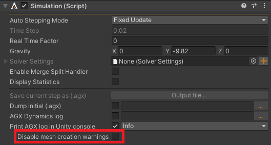
Mesh creation warnings can be disabled in the simulation inspector.
2.3.1.3. Web Debugger
AGX has a built in web debugger that ships with AGXUnity. The web debugger consists of two parts, a web debugging interface, and a remote debugging server that the debugging interface connects to. Both of these parts are accessed via the Simulation component. To start the web interface, simply press the Start Web Debugger button in the Simulation inspector. This spins up a temporary web server and opens a browser window.
After launching the web interface, the remote debugging server must be started before any data is displayed in the web debugger window. This is done by toggling the Enable Web Debugger checkbox in the simulation inspector.
It is not strictly necessary to launch the web debugger from within Unity, the server is also packaged with regular AGX SDK installations and that once launched, the browser window can be reused across multiple sessions.
Note
By default, the web debugger interface uses Z-up. To change this to Y-up as is common in Unity, click the settings icon in the top right corner of the web debugger window and change the up axis to Y.
2.3.2. Contact Material Manager
The Contact Material Manager is an optional singleton instance in a scene. When this manager is active, the list of Contact Materials are active and enabled.
Add Contact Material Manager to current scene by clicking
AGXUnity -> Managers -> Contact Material Manager from the main menu.
Defining Shape Material for Sphere and Ground. Contact Material and Friction Model for Sphere vs. Ground are created. The changes doesn’t have any effect until the Contact Material is added to the Contact Material Manager.
2.3.2.1. Defining oriented contact materials
It is common for objects to have geometries that cause their friction coefficients to differ depending on the direction of the friction force. In AGXUnity, this is can be modeled by creating a Contact Material, adding it to the contact material manager, and toggle the Is Oriented option in the list of contact material entries. This allows for defining a friction frame with a specified primary axis along which the X component of the friction coefficients will be applied. Any direction perpendicular to the main axis will apply the Y component instead.
Some collider types use special friction frames calculated by the model to make it easier to setup oriented friction (see Setting up track friction). In these cases, configuring oriented friction frames is not needed.
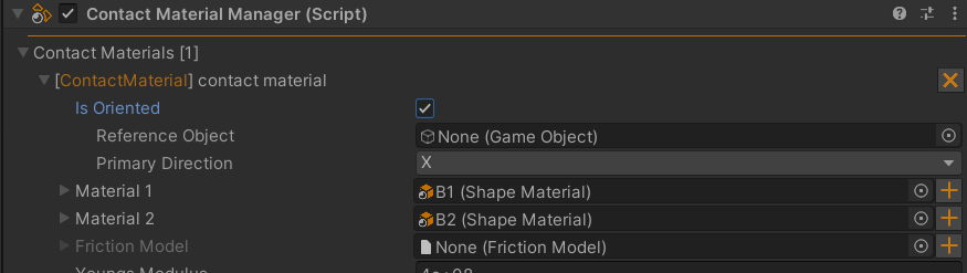
Options for oriented contact materials
2.3.3. Collision Groups Manager
The Collision Groups Manager is an optional singleton instance in a scene. When the manager is active, the list of collision group pairs will be disabled for collisions.
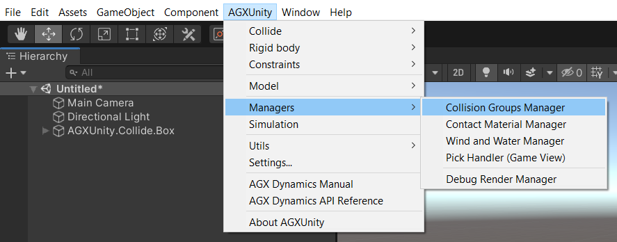
Add Collision Groups Manager to current scene by clicking AGXUnity -> Managers -> Collision Groups Manager
from the main menu.
To disable a pair use the Add pair panel where the groups may either be input as free text
or use the context menu ![]() for a list of all current Collision groups
in the current scene.
for a list of all current Collision groups
in the current scene.
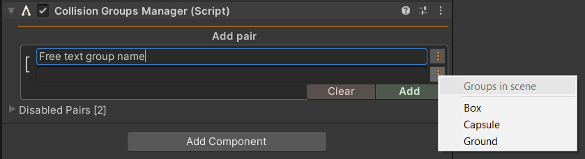
Add new disabled pair by typing the group name or click ![]() for a
list of all current Collision groups in the scene.
for a
list of all current Collision groups in the scene.
Note
The Collision Groups Manager adds the collision groups by hash. For this reason, if any collision
groups that are added by scripts have to be added by hash as well:
component.addCollisionGroup( "collisionGroup".To32BitFnv1aHash() )
2.3.4. Wind And Water Manager
The Wind And Water Manager is a single instance object that has to be added to the scene
to enable hydro- and/or aerodynamics. To add the Wind And Water Manager to a scene click
AGXUnity -> Managers -> Wind and Water Manager from the main menu.
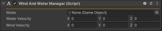
Wind And Water Manager Inspector with default values.
Property |
Description |
Default |
|---|---|---|
Water |
Water game object with one or several sensor shapes as children. |
null |
Water Velocity |
Velocity/Current in the water. |
(0, 0, 0) |
Wind Velocity |
Velocity/Wind for objects with aerodynamics enabled. |
(0, 0, 0) |
Note
Make sure each shape representing water has the Is Sensor toggle set (to true/enabled).
Note
Disable hydrodynamics for certain shapes by disabling collisions between the objects and the water shape(s).
WaterShape is a regular box and transforms into a water volume by enabling Is Sensor
and registering the instance to the Wind And Water Manager.
2.3.5. License Manager
The License Manager manages any AGX Dynamics for Unity license in Unity projects and builds.
The License Manager Window is opened from the main menu AGXUnity -> License -> License Manager.
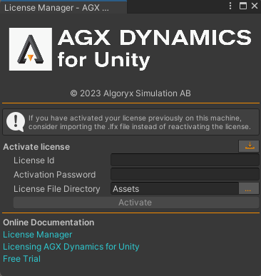
Default License Manager Window without any supported AGX Dynamics for Unity license files in the project. It’s possible to Activate a license, Refresh a license, Deactivate a license, inspect license data and copy an already existing license file to the current project.
While in the Unity editor, the Licence Manager searches for *.lfx files from the project root
directory. For example, if the project directory name is MyProject and AGX Dynamics for Unity is located at
MyProject/Assets/AGXUnity, it’s valid to place the license file anywhere where MyProject
is root, e.g., MyProject/AGX License/agx.lfx or MyProject/Assets/EditorStuff/agx.lfx.
In a build, the search is similar to while in the editor, but the root directory is the build directory,
where the main executable is located. If no valid *.lfx file is found, a similar search is made
for a Encrypted runtime license activation *.rtlfx file.
Note
Legacy license files, normally named agx.lic, are searched for similar to *.lfx
as a fallback when no *.lfx file is found. Previously to 3.0.0 (2021-07-01), the filename
was constrained to be agx.lic and located in pre-defined directories, but may from
3.0.0 (2021-07-01) be named *.lic and located in any directory under the Unity project
or build directory root.
2.3.5.1. Activate a license
A license is activated using a License Id and Activation Code and results in a
file (e.g., agx.lfx) that unlocks AGX Dynamics for the computer/hardware where
the activation took place. The license file may be copied and used in unlimited projects
and builds on the computer it was activated on, but the number of activations is limited
to something small, e.g., two where a developer has a stationary workstation and a laptop.
To activate a license using the License Manager Window, write your License Id and Activation Code into their respective text fields, select a target License File Directory where the generated license should be created, and click Activate. If the activation is successful, a license info section should appear with the generated license information, otherwise check the Unity Console for any warnings or errors.
To activate a license in a script:
// Check for already created, valid, .lfx and .lic files.
if ( !AGXUnity.LicenseManager.LoadFile() ) {
  // License hasn't been activated, activate the license and place
  // the generated agx.lfx in the 'dataPath' directory.
  var success = AGXUnity.LicenseManager.Activate( 123456,
                                                  "FOOBAR123",
                                                  Application.dataPath );
  // Unsuccessful, print status to the Console.
  if ( !success )
    Debug.Log( "Activation failed with status: " +
                AGXUnity.LicenseManager.LicenseInfo.Status );
}
The Licence Id and Activation Code is a document of value - avoid using the License Id and Activation Code in scripts. See Encrypted runtime license activation for more information how to activate runtime licenses.
2.3.5.2. Refresh a license
The license will occasionally automatically refresh itself with any updated information from the server. It’s possible to explicitly refresh a license by clicking 1) (figure below) of the license in the License Manager Window. Refreshed license information could be new expired date, enabled modules, etc.
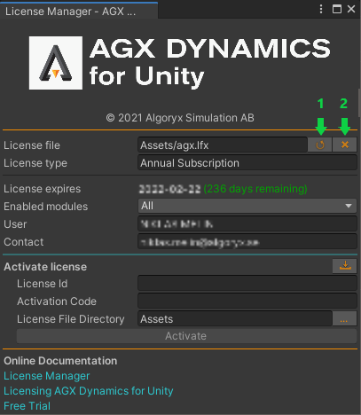
License Manager Window with one loaded, valid license. 1) Update license information/Refresh license from the license server. 2) Deactivate the license and delete the file, for the license activation to become available to activate on another device. 1) and 2) requires internet connection.
2.3.5.3. Deactivate a license
A deactivated license may be activated again, e.g., on another computer. The license file of a deactivated license is not possible to use, so it’s safe to delete the file after it has been deactivated.
To deactivate and delete a license from the License Manager Windows, click 2) of the license to deactivate and delete.
Deactivate a license and delete the file in a script:
using AGXUnity;

...

var file = LicenseManager.FindLicenseFiles( LicenseInfo.LicenseType.Service ).FirstOrDefault();
if ( !LicenseManager.DeactivateAndDelete( file ) )
  Debug.LogError( "Deactivate and delete failed: " + LicenseManager.LicenseInfo.Status );
2.3.5.4. Encrypted runtime license activation
The License Id and Activation Code of the runtime license can be encrypted with the final build.
The agx.rtlfx file containing the required data can be generated by opening the Runtime
Activation Generator window from the main menu: AGXUnity -> License -> Runtime Activation Generator.
This window is also opened automatically after a successful build with some of the required fields
filled out.
Note
The license information (id and activation code) isn’t tested to be valid against the server.
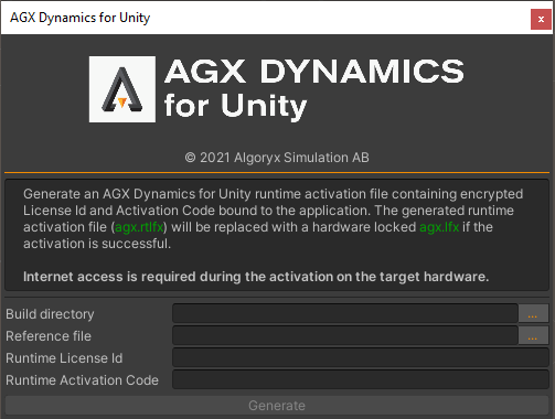
Runtime Activation Generator window with required fields.
The Reference File is a static file that is unique to your application and is used to encrypt and later decrypt the activation information. If the contents of the Reference File has been changed, the encrypted runtime license has to be re-generated.
The generated agx.rtlfx is placed in <build_directory>/<name>_Data/Plugins/x86_64/agx.rtlfx
and will be replaced by a hardware locked agx.lfx file in the same directory after a successful
license activation, the first time the application is started. This means that the default behavior is
to activate the license for the machine the application is started on, so if the application is tested
before being packaged, it’s important that the activated agx.lfx file is replaced by a backed up
version of the agx.rtlfx.
It’s also possible to take the contents from the .rtlfx file and manually activating it in a script.
using System.Linq;
using UnityEngine;
using AGXUnity;

namespace Scripts
{
  public static class RuntimeLicenseHandler
  {
    [RuntimeInitializeOnLoadMethod]
    public static bool ActivateUnlock()
    {
#if AGXUNITY_UPDATING
      // Avoiding calls to AGX Dynamics during updates.
      return false;
#else
      // Check if there's already an activated and valid license.
      var hasLoadedValidLicense = LicenseManager.LicenseInfo.IsParsed &&
                                  LicenseManager.LicenseInfo.IsValid;
      if ( hasLoadedValidLicense )
        return true;

      // Check if there's an existing license and try to load it if it exist.
      // If a license file exist we're not performing activation since the
      // current license could have expired or something else is wrong with it.
      // Another choice could be to delete the invalid license and try to
      // activate it again.
      var existingLicenseFile = LicenseManager.FindLicenseFiles().FirstOrDefault();
      if ( !string.IsNullOrEmpty( existingLicenseFile ) ) {
        // The license manager will log any status or errors.
        return LicenseManager.LoadFile( existingLicenseFile );
      }

      Debug.Log( "Activating AGX Dynamics for Unity license: " + s_activationContent );

      var licenseExt = LicenseManager.GetLicenseExtension( LicenseInfo.LicenseType.Service );
      var activatedLicenseDirectory = Application.dataPath;
      var activatedLicenseFilename = activatedLicenseDirectory + "/agx" + licenseExt;
      try {
        // Note that we're explicitly calling AGX Dynamics but some components here
        // in Unity relies on the AGXUnity.LicenseManager, so if successful, we
        // have to call UpdateLicenseInformation() on the license manager.
        var success = agx.Runtime.instance().activateEncryptedRuntime( s_activationContent,
                                                                       activatedLicenseFilename );
        if ( success ) {
          Debug.Log( "Successfully activated license: " + activatedLicenseFilename );

          // Make sure AGXUnity.LicenseManager.LicenseInfo is updated with our
          // newly activated license.
          AGXUnity.LicenseManager.UpdateLicenseInformation();
        }
        else
          Debug.LogError( "Failed to activate license: " + agx.Runtime.instance().getStatus() );

        return success;
      }
      catch ( System.Exception e ) {
        Debug.LogException( e );
        return false;
      }
#endif
    }

    private static readonly string s_activationContent = @"RT=XPbueSzfBeG3K2MlxBpf" +
                                                         @"EOfkWfqhEbM3qlIYWVw73I1" +
                                                         @"Vbml0eVBsYAllci5kbGwAcb" +
                                                         @"DONQhHsf7VoSyLYhfMGA==";
  }
}
2.3.5.5. Offline license activation
In the case when the Internet access is restricted or when the target computer doesn’t have an Internet connection at all, it’s possible to generate a license file using the following three steps:
Generate an XML document with unique encrypted data of the target computer (without Internet connection). Transfer the file on an USB stick or some other media to a computer with Internet access.
Upload the file or paste its content in the License Portal - Manual Request page, and download the response file (
response.xml). Copy the response file to the moveable media.Generate the license file (
agx.lfx) on the target computer given the response file.
Step (1) and (3) includes using the CLI of an application or Unity Editor project where AGX Dynamics for Unity is installed.
(1):
Generate the request file of a build containing AGX Dynamics for Unity:
# Usage: -generate-offline-activation <license_id>
#                                     <activation_code>
#                                     <optional_output_filename|license_activation_request.xml>
> MyApplication -quit -batchmode -nographics -generate-offline-activation 12345678 12AB23CD
Similar for the Unity Editor:
> path/to/unity/Unity -projectPath path/to/project ^
                      -quit -batchmode -nographics ^
                      -generate-offline-activation 12345678 12AB23CD
(3):
Generate the license file of a build containing AGX Dynamics for Unity:
# Usage: -create-offline-license <web_response_file> <optional_output_license_filename|agx.lfx>
> MyApplication -quit -batchmode -nographics -create-offline-license path/to/response.xml
Similar for the Unity Editor:
> path/to/unity/Unity -projectPath path/to/project ^
                      -quit -batchmode -nographics ^
                      -create-offline-license path/to/response.xml
Note
Line break on Windows Batch is ^ and \ in most other shells.
It’s possible to do the steps using script(s), but it’s not very convenient when the procedure includes several manual steps.
using UnityEngine;

namespace Script
{
  public static class OfflineLicenseCreator
  {
    /// <summary>
    /// Verifying AGX Dynamics is properly loaded into this process.
    /// </summary>
    public static bool Initialize
    {
      get
      {
        return AGXUnity.NativeHandler.Instance.Initialized;
      }
    }

    public static void GenerateOfflineActivation()
    {
      if ( !Initialize ) {
        Debug.LogError( "Generate offline license activation failed - AGX Dynamics failed to initialize." );
        return;
      }

      if ( AGXUnity.LicenseManager.GenerateOfflineActivation( licenseId: 12345678,
                                                              licensePassword: "12AB34CD",
                                                              outputFilename: @"//USB_A/activation.xml",
                                                              throwOnError: false ) )
        Debug.Log( "Successfully generated activation.xml on device USB_A." );
      else
        Debug.LogError( "Failed to generate activation.xml, check console/log for further information." );
    }

    public static void CreateOfflineLicense()
    {
      if ( !Initialize ) {
        Debug.LogError( "Create offline license failed - AGX Dynamics failed to initialize." );
        return;
      }

      if ( AGXUnity.LicenseManager.CreateOfflineLicense( webResponseFilenameOrContent: "//USB_A/response.xml",
                                                         licenseFilename: "agx.lfx",
                                                         throwOnerror: false ) )
        Debug.Log( "Successfully create license file agx.lfx." );
      else
        Debug.LogError( "Failed to create license file, check console/log for further information." );
    }
  }
}
2.3.6. Update Handler
Update Handler is a generic name of a self contained, editor only assembly, located in the
AGXUnity/AGXUnityUpdateHandler directory, introduced in version 2.4.3 (2021-06-17).
The aim of this manager is to handle and resolve issues during imports/updates of
AGX Dynamics for Unity packages.
During an update to a new version, AGX Dynamics for Unity is deleting all scripts and assets under its
root directory, normally Assets/AGXUnity, before importing the new version. This works
great in Unity versions 2019.3 and earlier but may result in various issues in Unity 2019.4
and newer. The source of the issues are unknown but the resulting errors are solely isolated
to AGX Dynamics for Unity, meaning it’s always possible close Unity, delete the AGXUnity directory,
start Unity and import the new version - which is not a viable solution. This Update Handler
is trying to resolve the issues before manual delete and import is necessary.
2.3.6.1. Update from 2.4.2 and earlier to 2.4.3 and later
Given you’re a current user with AGX Dynamics for Unity version 2.4.2 (2021-06-03) or earlier, and desire to update to version 2.4.3 (2021-06-17) or later, please follow these steps:
Download the
AGXUnityUpdateHandlerpackage.Import the package into the project in which you desire to update AGX Dynamics for Unity.
Update AGX Dynamics for Unity following the steps described in Updating the plugin.
2.3.6.2. Manual recovery from errors after update
If update has been made in a Unity version 2019.4 or newer without this Update Handler, it’s possible to perform the steps manually.
Right click the
AGXUnitydirectory in Project View and selectReimport.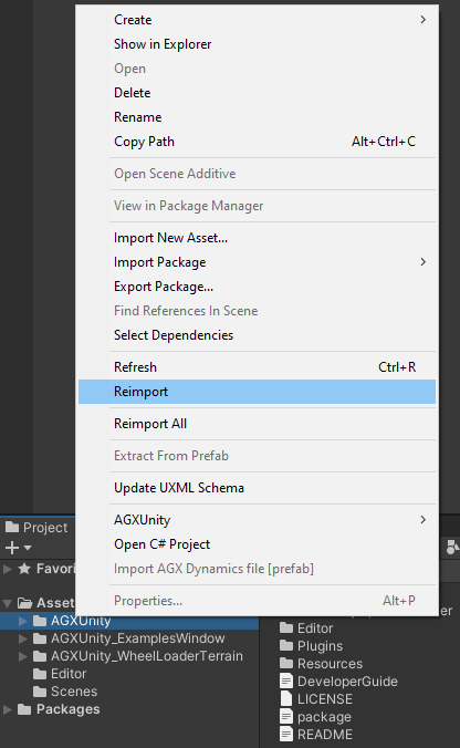
If
Reimportisn’t enough (Unity version 2020.1 or newer), add anyDefine SymbolunderEdit -> Project Settings... -> Player -> Scripting Define Symbolsand clickApplyto trigger a project wide compilation. The define symbol may be removed later on.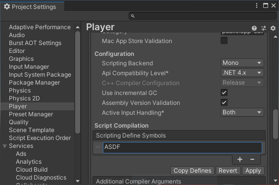
2.3.7. Debug Render Manager
The Debug Renderer Manager is a single instance object which is added to the scene to visualize
the physics simulation without having to add explicit shape visuals or render data to the components.
To add the Debug Render Manager to the scene click AGXUnity -> Managers -> Debug Render Manager
from the top menu.
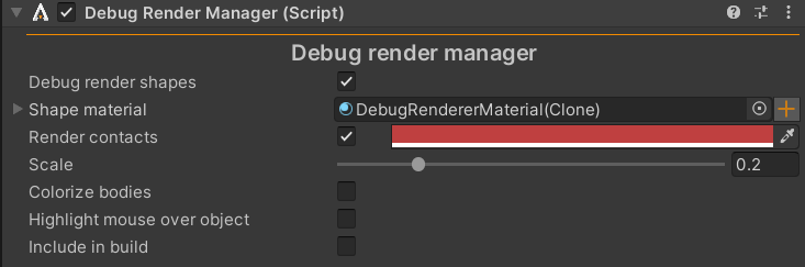
Debug Render Manager with default values.
Property |
Description |
Default |
|---|---|---|
Debug Render Shapes |
Whether or not to debug render the Shapes components in the simulation. |
false |
Shape Material |
The material used to render the debug shapes. |
- |
Render Contact |
Whether to render contacts in the simulation and the color to render them in. |
true |
Scale |
The scale of the rendered contacts. |
0.2 |
Colorize Bodies |
Give each Rigid Body wireframe a distinct color to make them easier to distinguish. (Not the shape debug visual) |
false |
Hightlight Mouse Over Object |
Highlights the Rigid Body currently under the cursor (if any). |
false |
Include In Build |
Whether to include the debug renderer in the built application as well. |
false |
2.4. Assets
Many configuration objects can be shared between multiple component instances. These objects make use of the Unity asset system to store configuration files to disk and to share configurations between components.
2.4.1. Shape Material
The Shape Material asset mainly used to define how two objects interact through a Contact Material which contains the parameters. Shape Material only has a few parameters which are used independent of Contact Material.
To create a new Shape Material, right click the project view and click AGXUnity -> Shape Material.
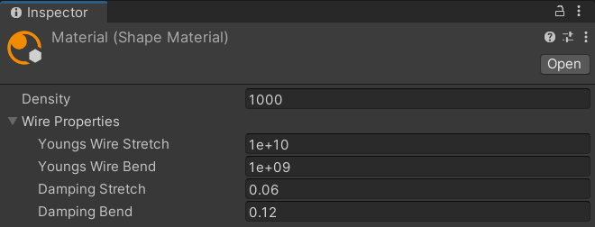
Shape Material Inspector with default values.
Property |
Description |
Default |
|---|---|---|
Density |
Density of an object with this material - affects the total mass of the object. |
1000 |
Youngs Wire Stretch |
Young’s modulus stretch of Wire instances with this material. |
1.0E10 |
Youngs Wire Bend |
Young’s modulus bend of Wire instances with this material. |
1.0E9 |
Damping Stretch |
Stretch damping of Wire instances with this material. |
0.06 |
Damping Bend |
Bend damping of Wire instances with this material. |
0.12 |
2.4.2. Contact Material
The Contact Material asset is an essential piece for computational performance, accuracy and stability of objects in contact. A Contact Material defines how two interacting Shape Materials behaves.
To create a new Contact Material, right click the project view and click AGXUnity -> Contact Material.
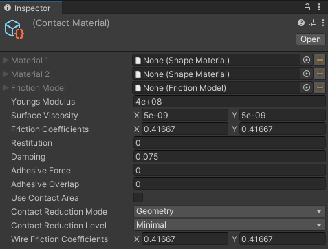
Contact Material Inspector with default values.
Property |
Description |
Default |
|---|---|---|
Material 1 |
First Shape Material - may be the same as Material 2 but invalid if null. |
null |
Material 2 |
Second Shape Material - may be the same as Material 1 but invalid if null. |
null |
Friction Model |
Friction Model of the contact material - Default Friction Model if null. |
null |
Youngs Modulus |
Elasticity of the two interacting Shape Materials. |
4.0E8 |
Friction Coefficient |
Primary direction and secondary direction friction coefficients. |
(0.417, 0.417) |
Restitution |
Restitution when the Shape Materials are impacting. |
0.0 |
Damping |
Spook damping of the interacting Shape Materials. |
0.075 |
Adhesive Force |
Cohesion of the interacting Shape Materials. |
0 |
Adhesive Overlap |
Target overlap is by default 0, Adhesive Overlap enables x distance overlap to occur before the normal forces turns positive. This could be used to stabilize contacts or should be > 0 when Adhesive Force > 0. |
0 |
Use Contact Area |
Toggle calculation of the contact area between to interacting Shape Materials. Enabling this feature will make Youngs Modulus more accurate and the interactions more stable. |
false |
Contact Reduction Mode |
Contact reduction mode: None, Geometry (geometry vs. geometry) or All (rigid body vs. rigid body). |
Geometry |
Contact Reduction Level |
Contact reduction Level: Minimal, Moderate or Aggressive. |
Minimal |
Wire Friction Coefficient |
Friction coefficients used when a wire is interacting with other objects. The primary (x) friction coefficient is used along the wire and the secondary (y) is used along the contact edge on the other object. |
(0.417, 0.417) |
When a Contact Material asset has been created and configured it doesn’t affect simulations until the Contact Material has been registered to the Contact Material Manager in a scene.
Refer to Defining oriented contact materials on how to create contact materials with non-uniform friction coefficients.
2.4.3. Friction Model
The Friction Model asset defines how frictional contacts are solved. A Friction Model asset can be assigned to one or several Contact Materials.
To create a new Friction Model, right click the project view and click AGXUnity -> Friction Model.
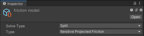
Friction Model Inspector with default values.
Property |
Description |
Default |
|---|---|---|
Solve Type |
Frictional contact solve type: Direct, Iterative, Split or Direct And Iterative. |
Split |
Type |
Frictional contact algorithm type: Iterative Projected Friction, Scale Box Friction, Box Friction or Constant Normal Force Box Friction. |
Iterative Projected Cone Friction |
Track Friction Model |
Whether or not this friction model is intended for use where one of the geometries is a track. See Setting up track friction |
False |
Box Friction is linear while Scale Box Friction is non-linear, meaning Box Friction is guessing the maximum friction forces, because the normal forces are unknown, while Scale Box Friction solves the system over and over again, adjusting the maximum friction forces given the current normal forces and friction coefficients.
Iterative Projected Friction is recovering the friction cone for any given solve type. This friction model is best suitable for grasping contacts and for anisotropic materials, where the primary and secondary friction coefficients aren’t equal.
Solve type Direct will feed the frictional contact to the direct solver, with accurate result but is likely to be more computationally expensive. Solve type Iterative will feed the frictional contact to the iterative solver, with far less accurate result but is far less computationally expensive. Solve type Split will warm start the iterative solver with normal forces calculated in the direct solver. Solve type Direct And Iterative solves the normal forces in the direct solver, estimates the frictional maximum force in the iterative solver (non-linear part solved in the iterative solver) and the maximum frictional force is fed to the direct solver.
2.4.3.1. Default Friction Model
The default friction model is Solve Type: Split and Type: Iterative Projected Friction.
2.4.4. Solver Settings
The Solver Settings asset containing AGX Dynamics solver and threading related settings. This asset can be added to the Simulation (Manager) in a scene.
To create a new Solver Settings asset, right click the project view and click AGXUnity -> Solver Settings.
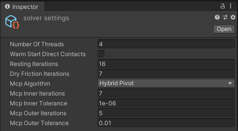
Solver Settings Inspector with default values.
Property |
Description |
Default |
|---|---|---|
Number Of Threads |
Number of threads available for AGX Dynamics. The initial value is calculated given the number of logical CPU cores divided by two minus one, but max four. |
|
Warm Start Direct Contacts |
Toggle warm start of frictional contacts solved with the direct solver. |
false |
Resting Iterations |
Number of iterations in the iterative solver. |
16 |
Dry Friction Iterations |
Friction refinement iterations during couplings of direct and iterative systems. |
7 |
Mcp Algorithm |
Mixed Complementarity Problem Algorithm used by the direct solver: Hybrid Pivot, Keller or Block Pivot. |
Hybrid Pivot |
Mcp Inner Iterations |
Maximum number of iterations (in the direct solver) to reach inner tolerance. |
7 |
Mcp Inner Tolerance |
Maximum tolerated residual of the solution. |
1.0E-6 |
Mcp Outer Tolerance |
Maximum number of non-linear iterations (in the direct solver) to reach outer tolerance. |
5 |
Mcp Outer Tolerance |
Maximum tolerated non-linear residual of the solution. |
1.0E-2 |
PPGS Resting Iterations |
Resting iterations for the Parallel Projected Gauss Seidel (PPGS) solver used in, e.g., Deformable Terrain. |
25 |
Note
It’s normally not necessary to change these values.
2.4.5. Cable Properties
The Cable Properties asset contains properties that controls the material properties of one or several cable instances. See AGX Dynamics Cable Properties documentation for more information regarding the cable properties.
Note
Plasticity
Yield Point is included in and the unused parameter Poisson's Ratio is excluded
from AGXUnity.CableProperties.
2.4.6. Cable Damage Properties
The Cable Damage Properties asset configures the Cable Damage visualization and calculation.
See AGX Dynamics Cable Damage documentation
for in-depth information on the cable damage system. To create a new Cable Damage Properties asset,
right click the project view and click
AGXUnity -> Cable Damage Properties.
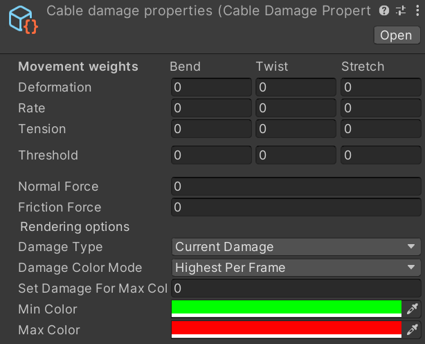
Cable Damage Properties Inspector with default values.
The Cable Damage visualization of the damage per segment can be configured through the Inspector on the
Cable Damage Properties asset. The current, or the accumulated, damage can be chosen to be visualized.
The visualization will adjust the color of the visual Material
of the CableRenderer component, as an interpolation between two colors, that can be configured.
The damage value for the minimum color is always 0, while the damage value for the maximum color can be
set as either some fixed value, or more adaptively as the largest damage value of the current simulation step.
This is configured with the Damage Color Mode setting.
Note
The default values are all 0 so no damage will be aggregated unless the properties are configured.
2.4.7. Deformable Terrain Material
Deformable Terrain Material properties related to Deformable Terrain instances. To create
a new Deformable Terrain Material asset, right click the project view and click
AGXUnity -> Deformable Terrain Material.
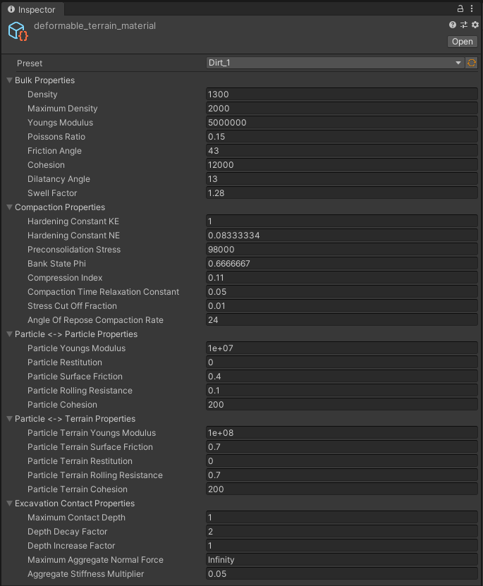
Deformable Terrain Material Inspector with default values.
2.4.7.1. Material Library
Starting from 2.1.0 (2020-06-26), AGX Dynamics for Unity and AGX Dynamics supports terrain material libraries where the
material parameters are defined in json files. The files are located in AGXUnity/Plugins/x86_64/agx/data/TerrainMaterials
and available materials are listed under Preset in the Inspector GUI.
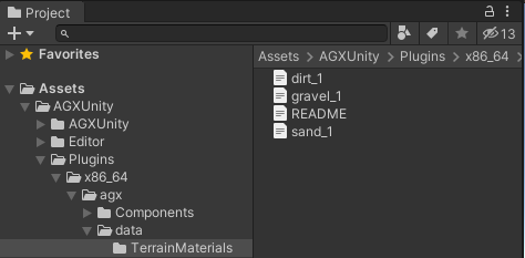
Project view of the location of the deformable terrain material library.
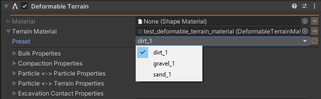
Inspector of available terrain materials.
To add a new material to the library, create a new file in the TerrainMaterials directory, e.g.,
my_soil_material.json:
{
   "BulkProperties" : {
      "cohesion" : 12000.0,
      "density" : 1300.0,
      "dilatancyAngle" : 0.2268928027592629,
      "frictionAngle" : 0.7504915783575616,
      "maximumDensity" : 2000.0,
      "poissonsRatio" : 0.150,
      "swellFactor" : 1.280,
      "youngsModulus" : 5000000.0
   },
   "CompactionProperties" : {
      "angleOfReposeCompactionRate" : 24.0,
      "bankStatePhi" : 0.6666666666666666,
      "compactionTimeRelaxationConstant" : 0.050,
      "compressionIndex" : 0.110,
      "hardeningConstantKE" : 1.0,
      "hardeningConstantNE" : 0.08333333333333333,
      "preconsolidationStress" : 98000.0,
      "stressCutOffFraction" : 0.010
   },
   "ExcavationContactProperties" : {
      "aggregateStiffnessMultiplier" : 0.050,
      "depthDecayFactor" : 2.0,
      "depthIncreaseFactor" : 1.0,
      "excavationStiffnessMultiplier" : 1.0,
      "maximumAggregateNormalForce" : "inf",
      "maximumContactDepth" : 1.0
   },
   "ParticleProperties" : {
      "adhesionOverlapFactor" : 0.050,
      "particleCohesion" : 200.0,
      "particleFriction" : 0.40,
      "particleRestitution" : 0.0,
      "particleRollingResistance" : 0.10,
      "particleTerrainCohesion" : 200.0,
      "particleTerrainFriction" : 0.70,
      "particleTerrainRestitution" : 0.0,
      "particleTerrainRollingResistance" : 0.70,
      "particleTerrainYoungsModulus" : 100000000.0,
      "particleYoungsModulus" : 10000000.0
   },
   "description" : "This material specification is named my_soil_material."
}
Change Preset in the Deformable Terrain instance(s) that should use the new material.
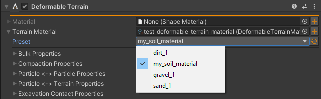
New terrain materials appears in the Deformable Terrain Material Inspector under Preset.
2.4.8. Deformable Terrain Properties
Properties related to Deformable Terrain instances. To create a new Deformable Terrain
Properties asset, right click the project view and click AGXUnity -> Deformable Terrain Properties.
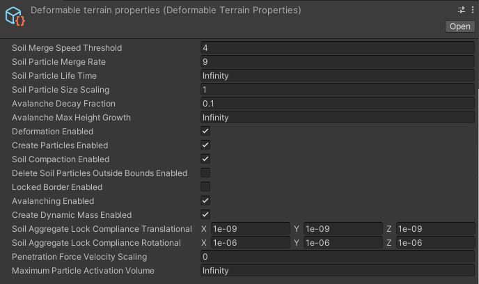
Deformable Terrain Properties Inspector with default values.
2.4.9. Deformable Terrain Shovel Settings
Settings related to Deformable Terrain Shovel instances. To create
a new Deformable Terrain Shovel Settings asset, right click the project view and click
AGXUnity -> Deformable Terrain Shovel Settings.
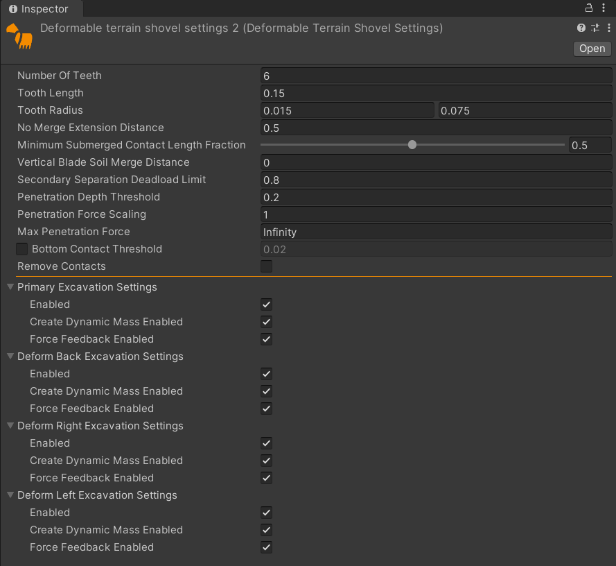
Deformable Terrain Shovel Settings Inspector with default values.
2.4.10. Track Properties
Properties related to Track instances. To create a new Track Properties asset, right
click the project view and click AGXUnity -> Track Properties.
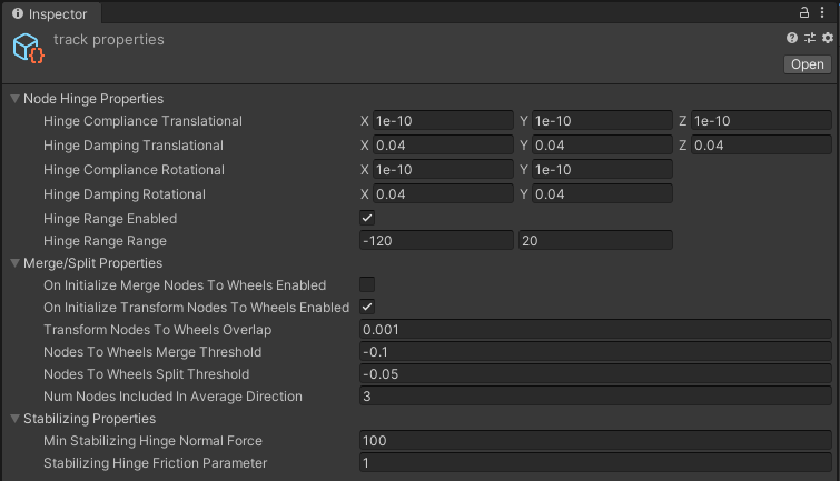
Track Properties Inspector with default values, except for the FullDoF option being toggled.
Note that the FullDoF toggle does not limit the ability to use an instance of the properties to on or the other, but rather is intended to make it easier to find the relevant properties for the Low DoF model.
See Track Properties documentation for detailed information about each property.
2.4.11. Track Internal Merge Properties
Internal merge properties related to Track when using the Full DoF model. To create a new Track Internal Merge Properties
asset, right click the project view and click AGXUnity -> Track Internal Merge Properties.
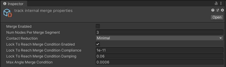
Track Internal Merge Properties Inspector with default values.
These properties controls if and how the track instance merge neighboring nodes for increased
computational performance. Merged nodes split when in contact with Sprocket or Idler,
or with another Track Wheel type with Split Segments property enabled.
2.4.12. Two Body Tire Properties
Properties related to Tire instances when using the Two Body Tire model. To create a new Tire Properties asset, right
click the project view and click AGXUnity -> Two Body Tire Properties.
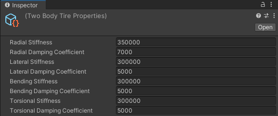
Two Body Tire Properties Inspector with default values.
See Tire Properties documentation for detailed information about each property.
2.4.13. Steering Parameters
Parameters related to Steering instances. To create a new Steering Parameters asset, right
click the project view and click AGXUnity -> Steering Parameters.
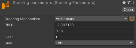
Steering Parameters Inspector with default values.
See Steering Parameters documentation for detailed information about each parameter.
2.4.14. Geometry Contact Merge Split Thresholds
Contact thresholds related to Merge Split Properties. To create a new Geometry Contact
Merge Split Thresholds asset, right click the project view and click
AGXUnity -> Geometry Contact Merge Split Thresholds.
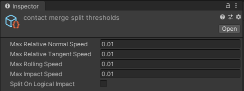
Geometry Contact Merge Split Thresholds Inspector with default values.
2.4.15. Constraint Merge Split Thresholds
Constraint thresholds related to Merge Split Properties. To create a new Constraint Merge
Split Thresholds asset, right click the project view and click
AGXUnity -> Constraint Merge Split Properties.
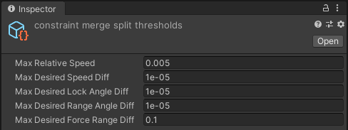
Constraint Merge Split Thresholds Inspector with default values.
2.4.16. Conveyor Belt Properties
This asset contains the compliance of the constraints linking the individual tracks which make up the Conveyor Belt.
To create a new Conveyor Belt Properties asset, right click the project view and click AGXUnity -> Conveyor Belt Properties.
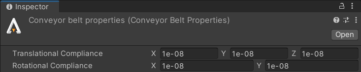
Conveyor Belt Properties Inspector with default values.
2.4.17. Lidar Surface Material Definition
This section describes a family of assets which are used to configure the surface parameters used to simulate LiDAR-rays bouncing off of objects in the scene, see Livox Models for more details of how to apply materials to an object in the scene. The specific parameters used vary between the specific model used. For a more in-depth description of surface materials, please refer to the relevant section in the AGX Dynamics User Manual
2.4.17.1. Opaque Lambert Surface
This is the simplest surface material model available in the LiDAR simulation and generally works well enough in most cases for modelling non-mirror-like surfaces. When no material is specified, and no other explicit default material is set in the Sensor Environment, objects in the LiDAR simulation use this material model with a roughness parameter of 0.8 as the default. See the section in the AGX Dynamics User Manual for more information.
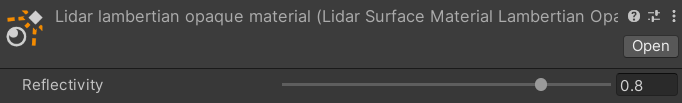
Opaque Lambert Surface Material Definition Inspector with default values.
2.4.17.2. GG-X and Oren-Nayar Surface
This is a more complicated material that describes a surface with a GG-X microfacet specular top-layer and a secondary Oren-Nayar rough diffuse layer. See the section in the AGX Dynamics User Manual for more information as well as the BRDF function definition.
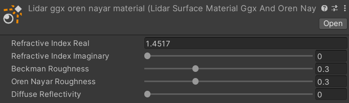
GG-X and Oren-Nayar Surface Definition Inspector with default values.
2.4.17.3. Explicit BRDF Surface
If the other material types are not able to model a specific BRDF, the BRDF function can be sampled and provided
to an explicit BRDF material. Note that this is not explicitly supported via AGXUnity assets but can be achieved by extending the base
AGXUnity.Sensor.LidarSurfaceMaterialDefinition class.
2.4.18. Lidar Ambient Materials
AGX LiDAR simulation allows for specifying an ambient material used to simulate various atmospheric effects. These materials can be added to the Sensor Environment to add them to the LiDAR simulation.
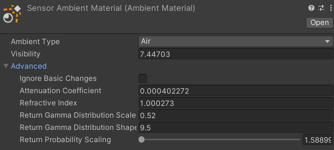
Lidar Ambient Material Inspector with default values.
To make it easier to get started with ambient materials, AGX provides four simplified ambient material models that model common weather phenomena:
Air - Configures the ambient material with the transmission parameters expected in regular air at a given visibility, as expected by inverse meteorological optical range (MOR).
Fog - Configures the ambient material with the transmission parameters expected in foggy conditions, as described by the Al-Naboulsi model, at a given visibility and signal wavelength. A maritimeness parameter can be used to specify an interpolation value between fine droplet continental radiation fog (0.0) and large droplet maritime fog (1.0).
Rainfall - Configures the ambient material with the transmission parameters expected in rainy conditions, as described by the Carbonneau model, at a given precipitation rate. A tropicalness parameter can be used to specify an interpolation value between common rain of smaller drop size (0.0) and tropical rain of larger drop size (1.0).
Snowfall - Configures the ambient material with the transmission parameters expected in snowy conditions, as described by the Carbonneau model, at a given precipitation rate and signal wavelength.
Under the hood, using these predefined models set the advanced parameters of the ambient material. To configure another material than the ones specified by the simplified models, on need to set the advanced parameters manually. For more information on these, please refer to the AGX Dynamics Manual section on ambient materials.
2.5. Tools
2.5.1.  Create constraint tool
Tool to create and configure a new constraint.
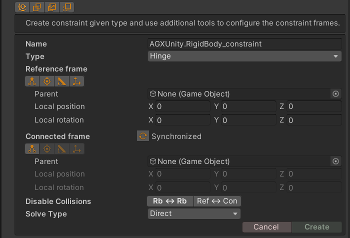
Create constraint Inspector dropdown tool.
Verify/select name.
Choose constraint type.
Configure reference frame.
Select parent of connected frame.
Select disabled collisions state - default is disabled.
Press Create to create the constraint - Cancel to discard any changes.
2.5.2.  Shape resize tool
Tool to change size of supported primitive shapes using arrow handles in Scene View. Supported shapes are:
The arrow handles are activated when this tool is active and when dragging any arrow in the
Scene View the shape is expanded in the direction of the mouse drag. For symmetric
resizing hold Left Shift.
Symmetric Left Shift and asymmetric resize of primitive shapes that supports
the shape resize tool.
Note
Previous to version 3.1.0 (2021-10-18), Left Ctrl had to be held down for
the resize handles to appear, and Left Ctrl + Shift for symmetric resizing.
2.5.3.  Shape given visual tool
Tool to create a collision primitive given a visual mesh. When the tool is selected on a rigid body,
a number of visual objects can be selected in the editor view. Use Shift select multiple objects and
Ctrl to toggle the selection of an object.
After a selection has been made, choose a primitive from the tool view to create an approximation for each of the selected visual objects using the given primitive. When hovering the primitive buttons, a preview of the shape which would be created is shown.
Note
While the tool attempts to find a good approximation for the primitive it is recommended to use this tool in conjunction with the shape resize tool to modify the created primitives manually after creation.
Creating collision geometry for a table model. Shift/Control is used to select all legs at once.
Note
When a primitive is created the tool is deactivated and it might appear that no changes were made to the Scene. This is because the newly created primitive has no visual element attached to it. For this reason, it can be useful to enable debug rendering while creating primitives for large scenes.
2.5.4.  Create visual tool
Tool to create visual representation of a shape or several shapes, depending on context. When this tool is activated for a Rigid Body a list of all shapes that doesn’t already have a visual representation is shown. When this tool is activated for a Shapes instance, the tool will only affect that instance - independent of any further shape children to that shape.
All shapes are children to the rigid body. 1. Sphere visual is created using this tool with the sphere shape as context. 2. All the other shapes visuals is created using this tool with the rigid body as context. Note that the sphere doesn’t appear in the list when it already has visual representation. 3. Create a new material for the box and change color to red.
Note
AGX Dynamics for Unity has its own visual component to mark shapes with already created visuals.
This means that this tool will still try to create visual representations for objects
that already has a UnityEngine.MeshFilter.
2.5.5.  Disable collisions tool
Simple utility tool that adds unique group names to objects and then adds the group pair to Collision Groups Manager.
Disabling collisions between the rigid body box and other objects by selecting objects in Scene View.
2.5.6.  Select parent tool
Tool to select/change a parent in a frame, by selecting an object in Scene View.
Configuring a hinge by choosing reference frame parent and alternating the connected frame parent between the box and the cylinder.
2.5.7.  Find edge tool
Finds a parent object and relative transform given a triangle edge and a direction. This tool is convenient for initializing frames in constraints, tire/wheel, cable and wire routs.
This tool contains four stages:
Select parent tool to find the parent to the frame.
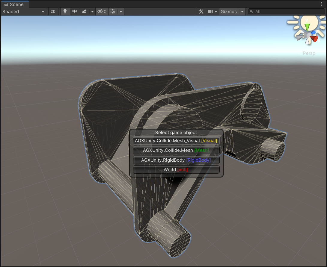
Select edge.
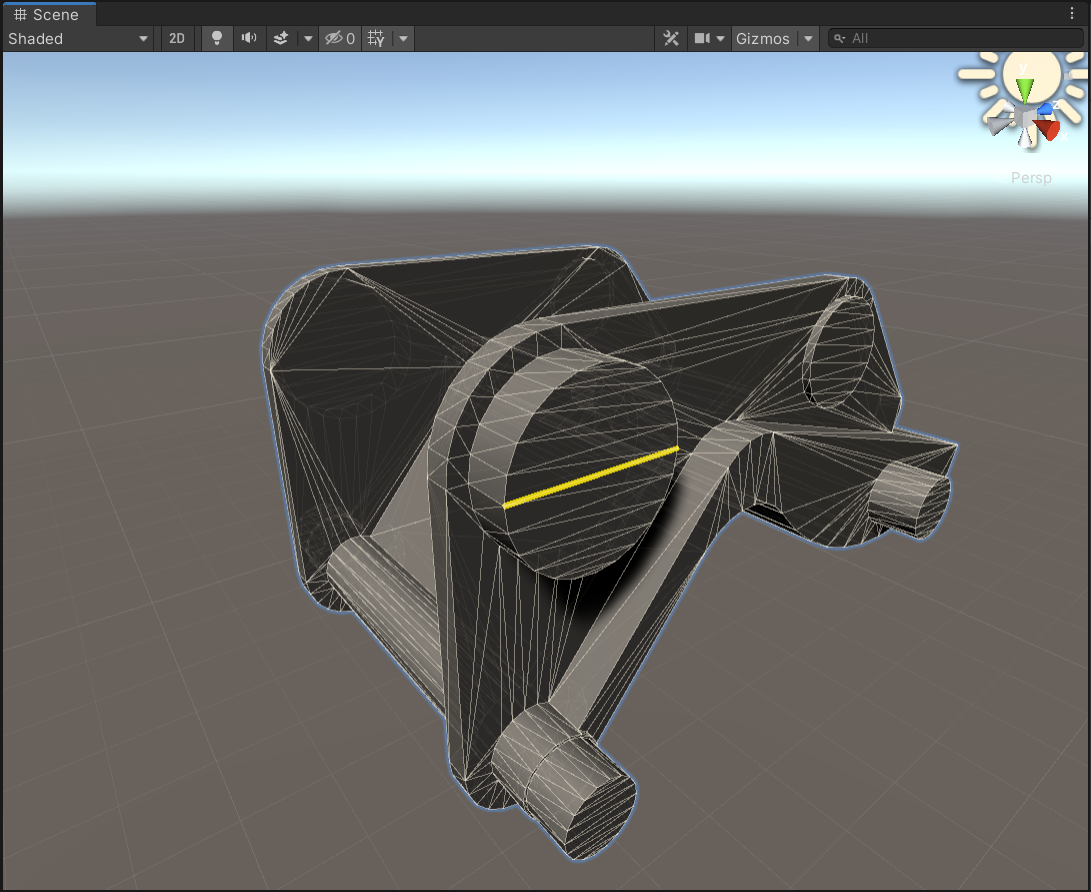
Select point on the selected edge. Note that the point snaps to begin, middle and end of the edge. For free move hold
Ctrl.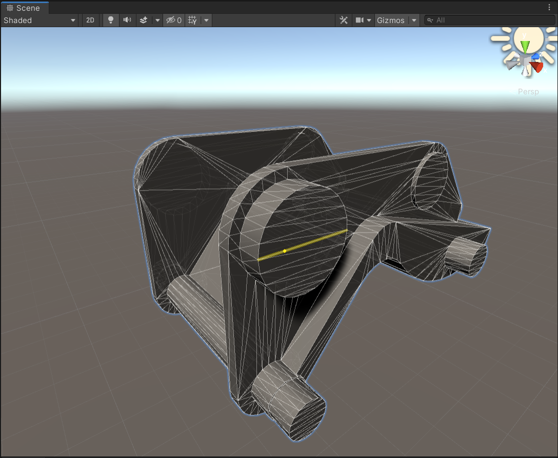
Select z direction of the final transform.
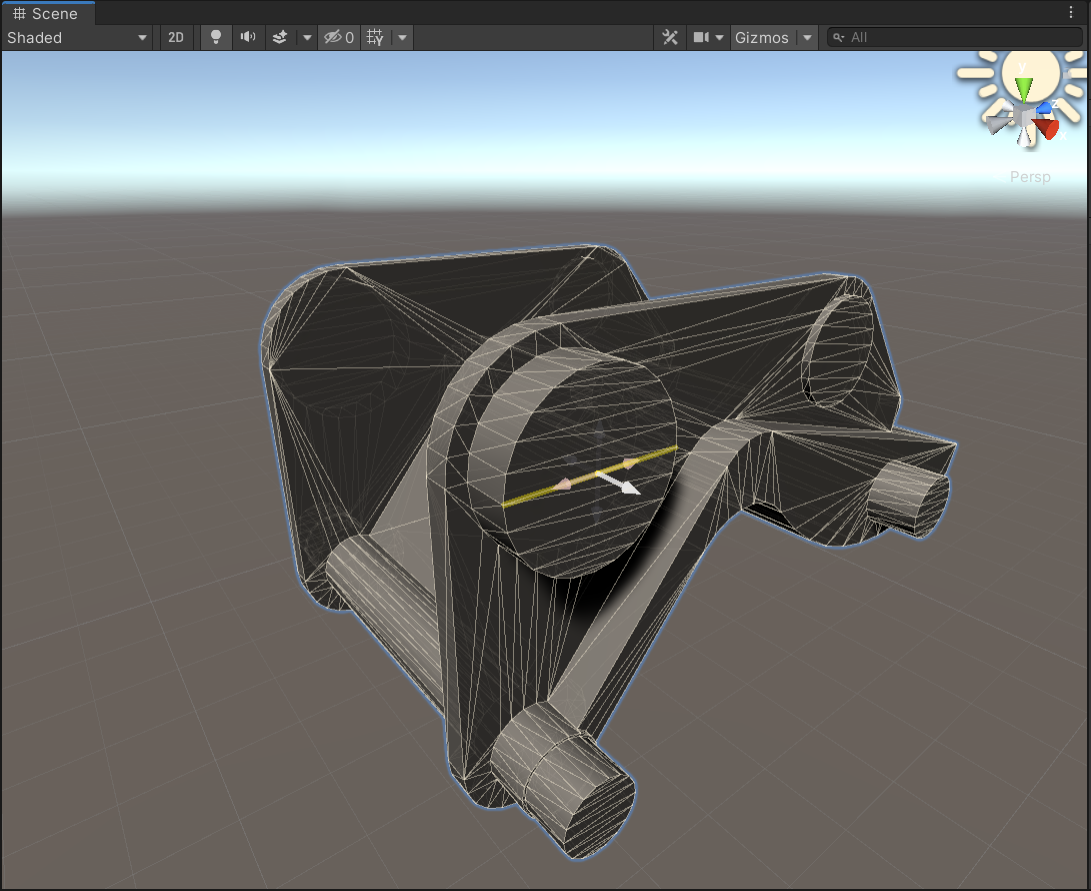
Creating two hinges, one on each side of the frame, using the Find edge tool.
2.5.8.  Find point tool
Find a parent object and relative transform given an object surface position and a direction. This tool is convenient for initializing frames in constraints, tire/wheel, cable and wire routes.
Configuring a hinge using the Find point tool.
2.5.9. Route from mesh tool
Uses a mesh to create a cable or wire route following the inner shape of the mesh. This tool can provide assistance when attempting to create a route for which a reference mesh exists. The tool also works well with the Unity package Splines providing a way of creating a cable or wire route from a spline.
Using a reference mesh to produce a cable route.
Default Behaviour By default, the tool assumes the cable/wire components parent as the source object and attempts to extract a mesh from a child of the object, but this mesh can be changed freely as well as the parent of the route either through the value field or through selecting an object in the scene, similarly to Select parent tool.
Aggressiveness The process of producing the inner structure from the mesh is dependent on an “Aggressiveness” factor which can be adjusted. Increasing this value can produce more detailed structures but with the drawback of introducing some artefacts. A value of 0-2 is typically sufficient, with the default settings mitigating most artefacts.
Preview and Editing It is also possible to preview and edit the structure before it is applied to the cable/wire component but some considerations should be done while doing so. The result of the initial generation is a graph of nodes, not necessarily without branches or cycles, and this graph is traversed in depth-first order to produce a valid route. When previewing this result, the visual is a filtered version of this produced graph
Holding any of the following keys enables interacting with the preview:
- Control
Enables adding new nodes at certain points in the structure by either interacting with nodes or edges. Interacting with a node forces the algorithm to reconsider that area of the mesh using two nodes instead of one. Interacting with an edge instead reconsiders the area in-between the two nodes in question, creating a new node in between them.
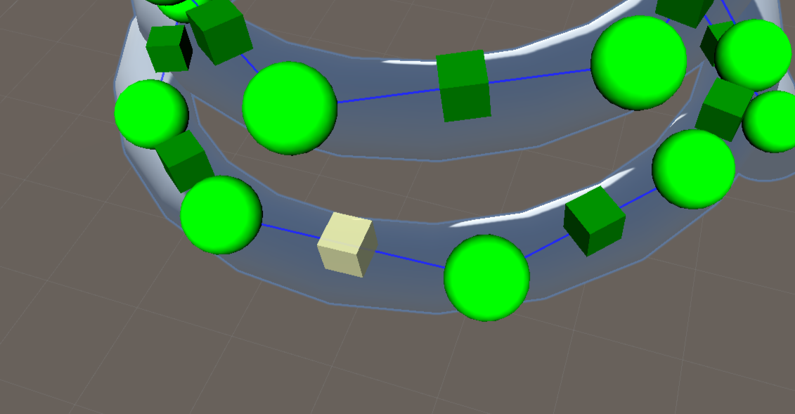
- Shift
Enables removing individual nodes in the structure. This also effectively removes the part of the mesh that the node is representing from the algorithm’s point of view, which will affect any subsequent addition of nodes.
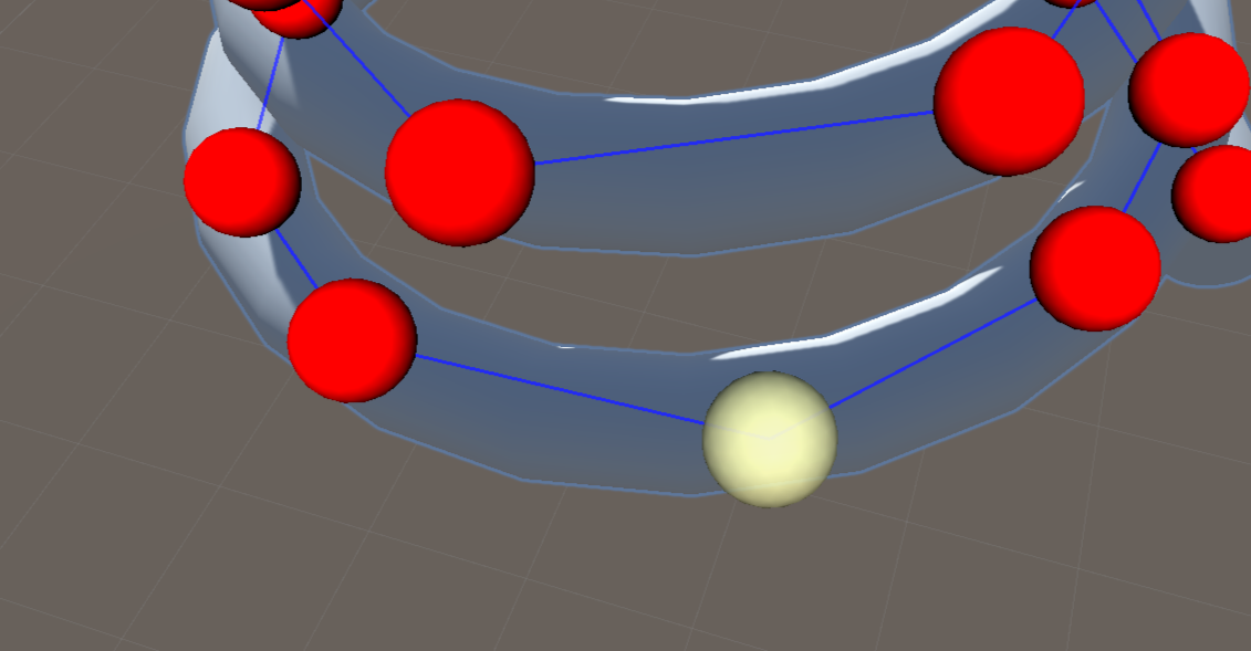
There is also a toggle which allows bypassing the filters to view the raw result of the algorithm. This can be useful in situations where the result is a set of disjoint structures (possible when the input mesh is disjoint) or when the depth-first order structure is misrepresenting the intended cable route.
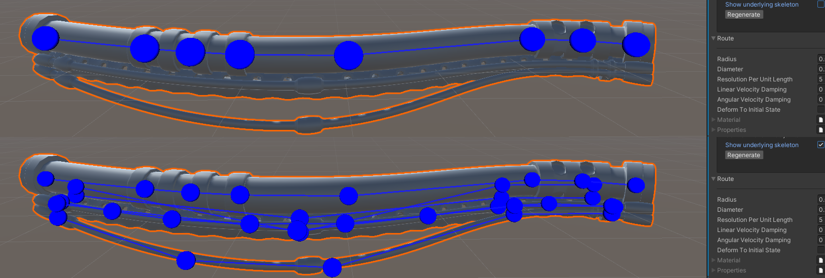
Automatic Upscaling The tool can also attempt to automatically upscale the structure given a target number of nodes. The number displayed in the tool can be manually changed which will prompt the tool to attempt to produce that many nodes. This is not always possible since it tries to guarantee a certain quality and neither is removing nodes in this way, e.g. inputting a smaller number of nodes than currently exist.
Using automatic upscaling to produce a cable route.
2.5.9.1. Input Mesh Considerations
The quality of the base mesh has a great effect on the quality of the output of the tool. While watertightness and manifoldness are not required for the algorithm to work they do ensure a better result, especially in the case of disjointness, and a well-distributed mesh also helps stabilize the result.
Note that a disjoint mesh is guaranteed to produce a disjoint structure, which means that a part of the mesh will be discarded for the resulting structure. Additionally, a mesh without watertightness (e.g. a cable without capped ends) will produce a different result than one with capped ends. The algorithm used considers the faces of the mesh and approximates the area spanned by a set of them, which means that any part of the mesh with implied faces is not considered at all by the tool.
2.5.9.2. Usage with Unity Splines
The Splines package enables spline creation and editing in Unity along with some other functionality which can be used in conjunction with the route from mesh tool. Using the ‘Spline extrude’ script, a spline can be dynamically translated into a mesh in Unity. This mesh exists just as any other mesh does and as such can be used as the mesh input for this tool, allowing a very dynamic way of creating routes.
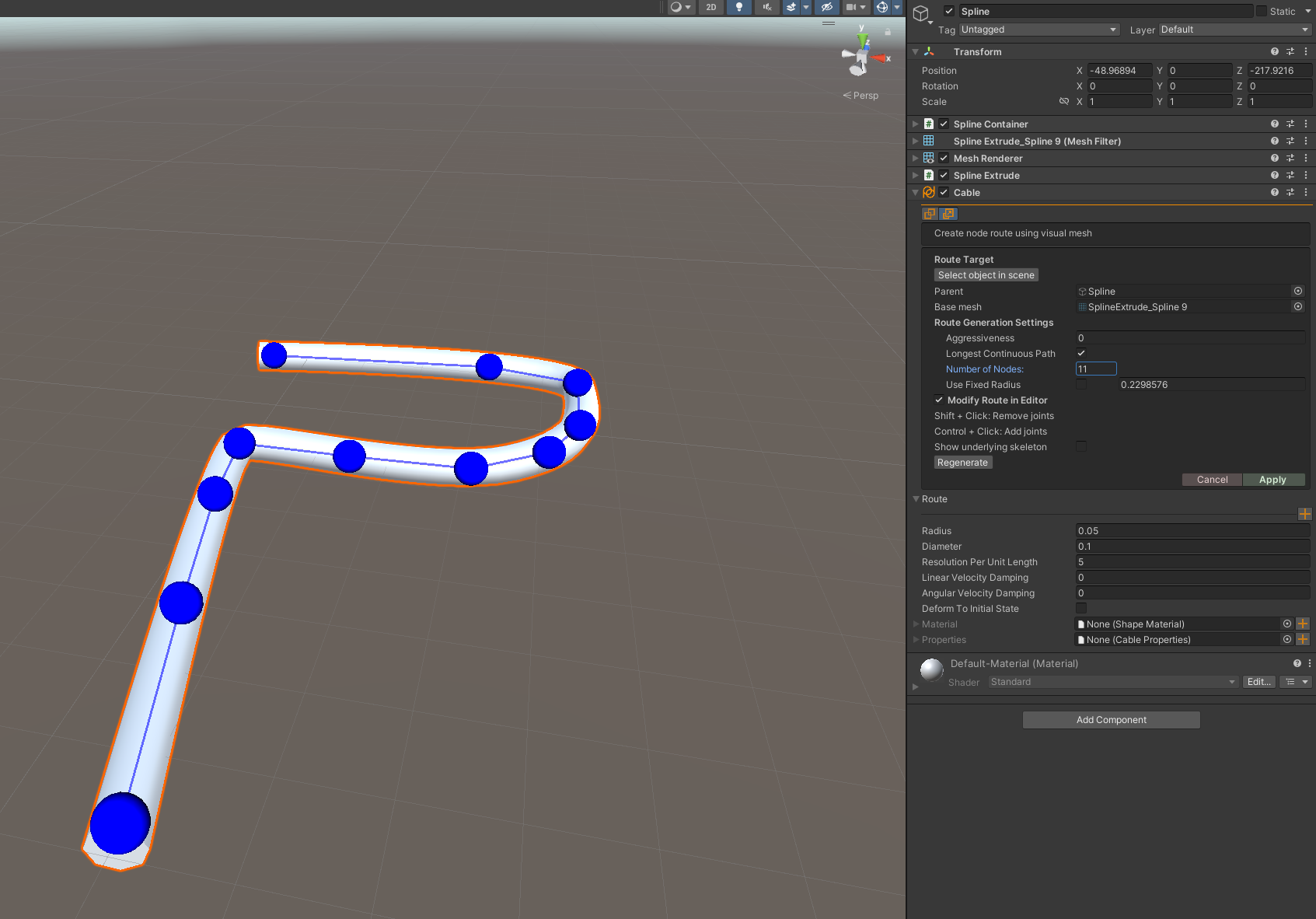
2.6. Utilities
2.6.1. PhysX to AGX Conversion Tool
The PhysX to AGX Conversion Tool can help migrating plain PhysX assets to AGX assets in Unity projects. This simplifies using existing Unity assets and ensures compatibility with AGX Unity workflows. The tools is available at the main menu under Utils.
Disclaimer: AGX and PhysX differ significantly, so conversions are rarely straightforward. The tool works only with select PhysX components; others might appear in the list but remain unselectable. The convertible components are:
UnityEngine.Rigidbody
UnityEngine.BoxCollider
UnityEngine.SphereCollider
UnityEngine.CapsuleCollider
UnityEngine.MeshCollider
UnityEngine.TerrainCollider
Note
Always create a backup of your project before running the conversion in the Prefab list, to prevent unintended data loss.
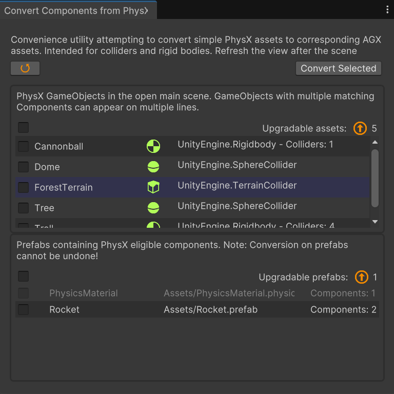
2.6.1.1. Scene GameObject List
GameObjects in the current (main) scene with identified PhysX components. Each entry shows: the GameObject name and the component type (e.g., UnityEngine.TerrainCollider), and the number of convertible assets. Clicking an object will highlight it in the Hierarchy.
GameObject Name: The name of the GameObject with the component.
Component Type: The name and icon of the identified PhysX component.
Collider Count: Only for PhysX Rigidbodys: The number of Colliders on or below that RB.
2.6.1.2. Project Prefab List
Prefabs from the entire project that has PhysX components eligible for conversion. Prefabs with only non-eligible will not be shown. Clicking one will highlight it in the Project view. Each entry includes:
Prefab Name: The name of the prefab containing the component.
Asset Path: The location of the prefab in the project directory.
Component Count: The number of convertible components in the prefab.
2.6.1.3. Usage tips
Check the box for each asset to convert, then press the Convert selected button to proceed.
Always double check results! The old physics might have properties that were not carried over and there are more settings in AGX than PhysX.
Select all in each box by clicking the box at the top of each table.
Multiple Components: If a GameObject has multiple components of the same type, it will appear on separate lines. Only the components selected will be converted.
Undo Scene Object Conversions: If converting only Scene objects, use Undo to revert the conversion.
Only the active scene The tool does not have an option to walk through other scenes than the main scene.
Terrain is treated a bit special depending on whether it has neighbors or not. If it has, then a Deformable Terrain Pager is added, otherwise it will be a Deformable Terrain.
In Play Mode only Components in the scene are convertible, but use it on your own risk…
Refresh the view if the scene or prefabs changes.
2.7. File Import/Export
Unity supports import of several 3D formats (.fbx, .dae, .3ds, .dxf,
.obj, .skp). AGX Dynamics for Unity supports additional imports, both pure mesh data (.stl)
and physics decorated (.agx, .aagx, .urdf).
2.7.1. URDF Import
AGX Dynamics for Unity supports reading Unified Robot Description Format (URDF) files
into an easily queryable structure (AGXUnity.IO.URDF.Model) which contains all the data.
There are many options what to do with the model data - it can for example be instantiated in a scene with AGX Dynamics for Unity physics components and game objects.
Note
If the collision shape is an imported model, such as .fbx or .dae, make sure the
collision data is accessible for the collision mesh to be created,
before the URDF model is imported.
Below is an example of a link and a joint from ABB IRB 5400
where link_3 and joint3 are expanded in the model tree with their corresponding
AGXUnity.RigidBody and AGXUnity.Constraint.
<link name="link_3">
  <visual>
     <geometry>
        <mesh filename="package://abb_irb5400_support/meshes/irb5400/visual/link_3.dae"/>
     </geometry>
     <material name="">
        <color rgba="0.7372549 0.3490196 0.1607843 1"/>
     </material>
  </visual>
  <collision>
     <geometry>
        <mesh filename="package://abb_irb5400_support/meshes/irb5400/collision/link_3.stl"/>
     </geometry>
     <material name="">
        <color rgba="1 1 0 1"/>
     </material>
  </collision>
</link>

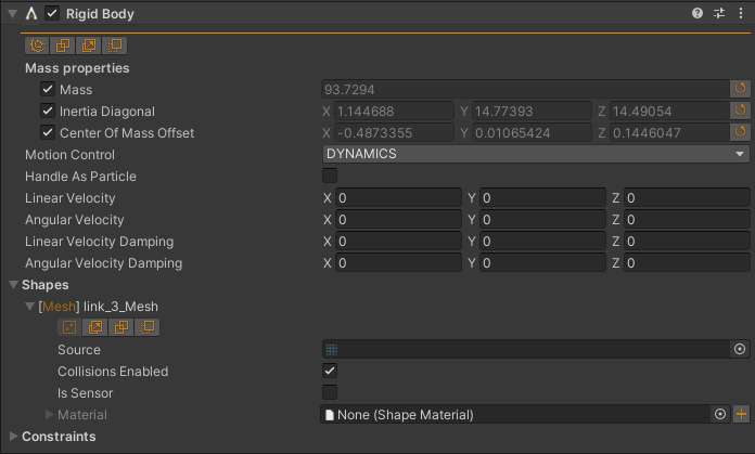
<joint name="joint3" type="revolute">
  <parent link="link_2"/>
  <child link="link_3"/>
  <origin rpy="0 0 0" xyz="0 0 1.200"/>
  <axis xyz="0 1 0"/>
  <limit effort="100" lower="-1.308" upper="1.308" velocity="2.3911"/>
</joint>
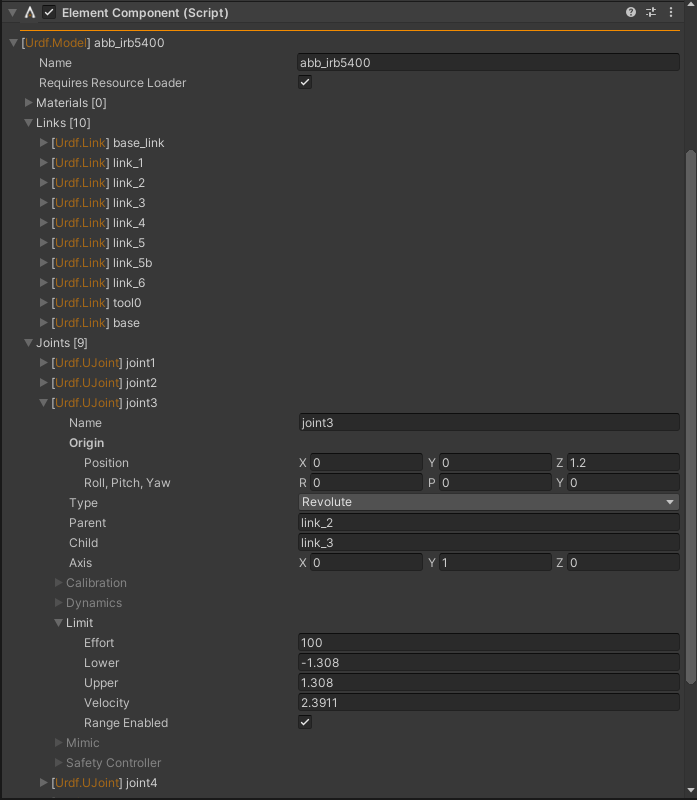
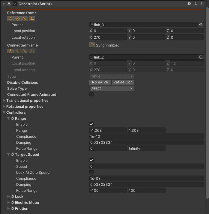
Note that the link_3 element doesn’t include an <inertial> definition so
the mass properties of link_3 is calculated given the shape defined under
<collision> (with default density 1000 kg/m3).
All defined data for link and link is read and stored in an instantiated
model. When some data requires context, it’s possible to access the original data from
anywhere suitable. For example joint <limit ... velocity="2.3911" .../> is, from
the specification, “An attribute for enforcing the maximum joint velocity.”. I.e., not the speed/velocity
to be assigned to the motor but rather a safety limit, defining the maximum velocity of the joint
(m/s for prismatic and rad/s for revolute/hinge). Below is an example script exemplifying how
to access the joint data and recover the joint <limit> element from the file. The
script is attached to the game object containing the AGXUnity.Constraint named joint3.
using UnityEngine;
using AGXUnity;
using AGXUnity.IO.URDF;

namespace Scripts
{
  public class UJointDataRead : ScriptComponent
  {
    protected override bool Initialize()
    {
      var jointData   = GetComponent<ElementComponent>().Element as UJoint;
      var limitData   = jointData.Limit;
      var maxVelocity = limitData.Velocity;
      Debug.Log( name + ": Maximum velocity is " + maxVelocity + "." );
      Debug.Log( "<limit effort=\"" + limitData.Effort + "\" " +
                        "lower=\"" + limitData.Lower + "\" " +
                        "upper=\"" + limitData.Upper + "\" " +
                        "velocity=\"" + limitData.Velocity + "\"/>" );
      return true;
    }
  }
}
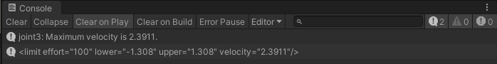
2.7.1.1. Reading an URDF model
Read a model given filename (including path) to an .urdf file.
try {
  var model = AGXUnity.IO.URDF.Model.Read( "Assets/URDF/my_robot.urdf" );

  Debug.Log( "#links: " + model.Links.Length );
  foreach ( var link in model.Links )
    Debug.Log( "    link: " + link.Name );

  Debug.Log( "#joints: " + model.Joints.Length );
  foreach ( var joint in model.Joints )
    Debug.Log( "    joint " + joint.Parent + " <-> " + joint.Child + ": " + joint.Name );
}
catch ( AGXUnity.UrdfIOException e ) {
  Debug.LogException( e );
}
Any error found in the file during parse will throw an AGXUnity.UrdfIOException stating
which line (in the URDF file) and what type of error occurred. If AGXUnity.IO.URDF.Model.Read
returns, the file is interpreted as valid and model in the above example wont be null.
To view the read data in the inspector - create a new game object, add the AGXUnity.IO.URDF.ElementComponent
to it and assign the model.
try {
  var model = AGXUnity.IO.URDF.Model.Read( "Assets/URDF/my_robot.urdf" );

  var go = new GameObject( model.name );
  go.AddComponent<AGXUnity.IO.URDF.ElementComponent>().SetElement( model );
}
catch ( AGXUnity.UrdfIOException e ) {
  Debug.LogException( e );
}
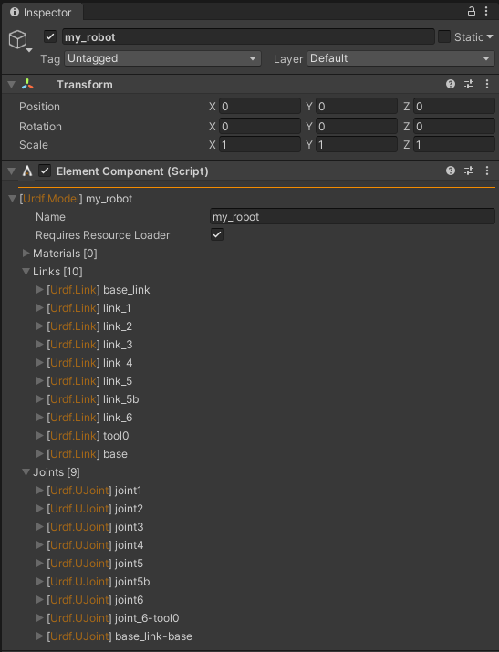
2.7.1.2. Instantiating an URDF model
There are several different scenarios where an URDF model can be instantiated in a scene. For example by selecting an URDF file in the Project tab, from an editor script or during runtime. Runtime instantiation is in general supported but it’s up to Unity and the user to manage any required resources. See URDF resources for further information.
2.7.1.3. URDF resources
URDF files either references external resources with relative path (with respect to the .urdf file),
e.g, <mesh filename="../meshes/my_robot/visual/base.dae"/>, or normally by using package://,
e.g, <mesh filename="package://my_robot_model/meshes/my_robot/visual/base.dae"/>, defining the resource
root directory. You either know the package root directory or you have to find it, and depending on in what context
the resource is loaded, the loading is different. During runtime the resource has to be found (and compatible
with Unity resources) in a Resources directory hierarchy and in the Editor it’s either
AssetDatabase.LoadAssetAtPath<GameObject> or manual handling if the format isn’t supported by Unity.
Instantiating a model will fail on any failed resource load.
Both AGXUnity.IO.URDF.Model and AGXUnityEditor.IO.URDF.Reader has a method CreateDefaultResourceLoader
taking dataDirectory as argument, convenient when you know the package root directory and in which context
the model is instantiated (Editor vs runtime). The difference is that AGXUnity.IO.URDF.Model.CreateDefaultResourceLoader
takes an additional argument resourceLoad which the AGXUnityEditor version is implementing as:
return Model.CreateDefaultResourceLoader( dataDirectory,
                                          ( filename, type ) =>
                                            AssetDatabase.LoadAssetAtPath<GameObject>( filename ) );
If the second argument is null (the actual resource load call), the load of resources will default
to UnityEngine.Resources.Load<Object>( filename ) which requires filename to be in the
Resources directory hierarchy and supported by Unity, except for .stl files which are handled
by the default resource loader.
Below is an example of a custom resource loader, assuming all resources referenced in the URDF file are STL files. The STL files are imported using STL Import which creates instances that has to be removed when the model has been instantiated.
using System;
using System.IO;
using System.Linq;
using System.Collections.Generic;

using UnityEngine;
using Object = UnityEngine.Object;

using AGXUnity.IO.URDF;
using AGXUnity.IO;

public static class IOUtils
{
  // This example only support load/instantiate of STL resources.
  public static Func<string,
                      Model.ResourceType,
                      Object> MyCustomResourceLoader( string dataDirectory = "",
                                                      Func<string,
                                                          Model.ResourceType,
                                                          Object> resourceLoad = null )
  {
    var loadedInstances = new List<GameObject>();
    Func<string, Model.ResourceType, Object> resourceLoader = ( resourceFilename, type ) =>
    {
      // Final call to this resource loader. We'll receive this
      // call even if the model contains errors. Destroy all
      // created instances.
      if ( type == Model.ResourceType.FinalizedLoad ) {
        loadedInstances.ForEach( instance => Object.DestroyImmediate( instance ) );
        loadedInstances = null;
        return null;
      }

      // Remove "package://" and/or include given dataDirectory.
      if ( resourceFilename.StartsWith( "package:/" ) )
        resourceFilename = dataDirectory + resourceFilename.Substring( "package://".Length );
      else if ( !string.IsNullOrEmpty( dataDirectory ) )
        resourceFilename = dataDirectory + resourceFilename;

      var isStlFile = Path.GetExtension( resourceFilename ).ToLower() == ".stl";

      // STL file we instantiate it and delete them at FinalizeLoad.
      if ( isStlFile ) {
        var stlInstances = StlFileImporter.Instantiate( resourceFilename );
        loadedInstances.AddRange( stlInstances );
        return stlInstances.FirstOrDefault();
      }
      return null;
    };
    return resourceLoader;
  }
}
2.7.1.4. Saving an URDF as prefab
URDF as assets and/or prefab was added in 3.1.0 (2021-10-18). It’s now possible to import an URDF model as
prefab by right clicking an URDF file in the project and navigate to AGXUnity -> Import -> Selected URDF [prefab]....
A folder panel will open for each selected, and successfully imported, model for the target directory of
the prefab and its assets.
Note
Re-import of a modified .urdf file isn’t supported. A new prefab will be created with a
different name if the prefab already exist in the target directory.
An instantiated URDF model contains instances of AGXUnity.IO.URDF.Element and may contain instances
of UnityEngine.Mesh and UnityEngine.Material. Unsaved mesh and material instances origins
from STL resources and URDF material declarations. If a game object of an URDF model is, e.g., drag-dropped
to the project to create a prefab, all the unsaved instances has to be saved as well before the prefab is
created. It’s not possible in Unity to know when a prefab is about to be created (e.g., when drag-dropped), so
saving the assets and/or prefab has to be done manually by clicking a button, using context menus or by
implementing a custom editor script.
Note
If all assets has been saved or already is on disk it’s possible to drag-drop the game object to create a prefab.
2.7.2. STL Import
The STL file format contains raw, unstructured triangle mesh data, i.e., only three vertices per triangle and one normal. No color, texture or other attributes (not entirely true). The binary version of the format leaves only 16 bits for additional information (“Attribute byte count”), but there’s no standard way to interpret this data (to, e.g., color) so AGX Dynamics for Unity ignores these additional 16 bits.
The importer supports both binary and ASCII STL files and either returns meshes read or instantiates
game objects with UnityEngine.MeshFilter and UnityEngine.MeshRenderer components in
the current scene. In either case, the meshes are currently only stored in memory even though instances
will be saved in the scene file (when the scene is saved).
Note
To determine if a file is ASCII or binary is in general not possible. AGX Dynamics for Unity
checks the first 256 bytes of the file and if at least one of the bytes is a control character
that’s not r || n || t the file is interpreted as a binary file. This means that,
e.g, if the name of a solid in an ASCII file contains a control character, the file will be
parsed as a binary file. It’s hard to do it the other way around because there’s a good chance
you’ll stumble upon a binary STL file starting with the characters “solid”.
2.7.2.1. Normals of a STL file
Per-triangle normal isn’t suitable for visuals mesh data. That’s why UnityEngine.Mesh is per-vertex
normal and AGX Dynamics for Unity STL importer is converting the STL normals to vertex normals with a smoothing angle
threshold - default 26 degrees. That means that when the angle between two triangle normals exceeds 26 degrees,
an average of the triangle normals will be used for the vertices involved.
Note
AGX Dynamics collision meshes recalculates the normals given vertices and triangle orientation so the smoothing angle threshold doesn’t affect the physics, meaning it’s possible, and suitable, to use the read meshes for both visual and collision meshes.
Below is an example of the default read STL mesh data (left) and the same mesh read with the default smoothing angle threshold (right).
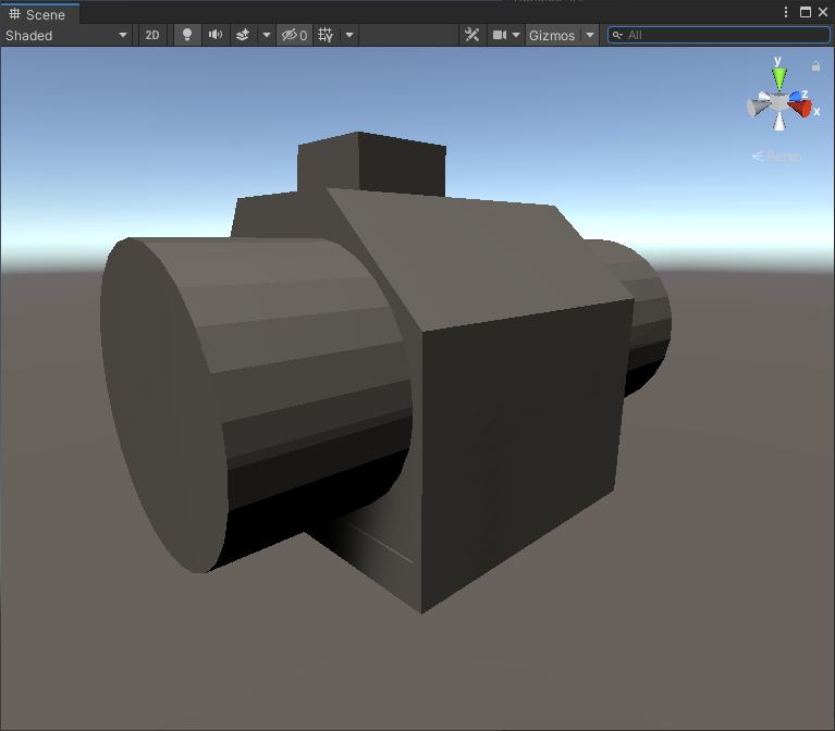

2.7.2.2. Read a STL file
The AGX Dynamics for Unity STL reader StlFileImporter is part of AGXUnity.IO meaning it’s possible to read and
instantiate STL meshes at runtime. Since UnityEngine.Mesh has a limit of 65535 vertices, the Read
methods returns an array of meshes rather than a single mesh.
Below is an example where a STL file is read and saved as an asset. If the STL file contains/is parse as several
meshes, the mesh data is stored in a single file but loaded as several UnityEngine.Mesh instances.
public static Mesh[] SaveStlMeshesToAssets( string filename, string directory )
{
  Mesh[] meshes = null;
  try {
    // Read meshes from given STL filename, e.g,
    // "Assets/STL/my_stl_file.stl" and 'directory'
    // is for example "Assets/STL_Exports".
    meshes = AGXUnity.IO.StlFileImporter.Read( filename );
    if ( meshes.Length == 0 )
      throw new AGXUnity.Exception( "Unable to parse mesh(es) from: " + filename );

    // Assuming 'directory' is relative to the project, i.e.,
    // starts with "Assets".
    directory = directory.Replace( '\\', '/' );
    if ( !System.IO.Directory.Exists( directory ) ) {
      System.IO.Directory.CreateDirectory( directory );
      AssetDatabase.Refresh();
    }

    // Creating the main mesh asset. If there are more than
    // one mesh this mesh will be main and the rest will be
    // saved in the same file.
    AssetDatabase.CreateAsset( meshes[ 0 ],
                               directory +
                                 '/' +
                                 System.IO.Path.GetFileName( filename ) +
                                 ".asset" );
    AssetDatabase.SetMainObject( meshes[ 0 ], AssetDatabase.GetAssetPath( meshes[ 0 ] ) );
    // We've already saved the first mesh, if there are more we
    // add the additional meshes to our main mesh (same file,
    // still individual meshes) - so for loop start from 1.
    for ( int i = 1; i < meshes.Length; ++i ) {
      if ( string.IsNullOrEmpty( meshes[ i ].name ) )
        meshes[ i ].name = "{meshes[ 0 ].name} (" + i + ")";
      AssetDatabase.AddObjectToAsset( meshes[ i ], meshes[ 0 ] );
    }

    AssetDatabase.SaveAssets();
    AssetDatabase.Refresh();
  }
  catch ( AGXUnity.Exception e ) {
    Debug.LogException( e );
  }

  return meshes;
}
2.7.2.3. Instantiate a STL file
Instantiating a STL file is similar to Read a STL file but the return value of AGXUnity.IO.StlFileImporter.Instantiate
is an array of game objects. An additional, optional, argument is a callback for each created UnityEngine.Object to, e.g.,
manage undo/redo in the editor or to further decorate the instances.
Below is an editor script that manages undo/redo of a STL file instance.
public static GameObject[] InstatiateStlUndo( string filename )
{
  var instances = new GameObject[] { };
  // Increment undo group and store id so that we can collapse
  // all changes into one undo/redo.
  Undo.IncrementCurrentGroup();
  var undoGroupId = Undo.GetCurrentGroup();
  try {
    // Callback from the STL Instantiate method for all
    // UnityEngine.Object created.
    System.Action<Object> onCreatedObject = createdObject =>
                                             Undo.RegisterCreatedObjectUndo( createdObject,
                                                                             "Created " +
                                                                               createdObject.name );
    // Instantiate given STL filename in the current scene.
    instances = AGXUnity.IO.StlFileImporter.Instantiate( filename,
                                                         onCreatedObject );
  }
  catch ( AGXUnity.Exception e ) {
    Debug.LogException( e );
  }
  finally {
    // Collapse all registered undo from onCreatedObject so that
    // the user doesn't have to press ctrl + z four times if one
    // game object, one mesh filter, one mesh and one mesh renderer
    // were created.
    Undo.CollapseUndoOperations( undoGroupId );
  }

  return instances;
}
Two other editor examples that supports undo/redo but these creates an AGXUnity.RigidBody with an
AGXUnity.Collide.Mesh. The first example assumes the STL file is only a single mesh, while the second
doesn’t use AGXUnity.IO.StlFileImporter.Instantiate (which creates one game object per created mesh)
and instead use AGXUnity.IO.StlFileImporter.Read to get all meshes and instantiates one AGXUnity.RigidBody
with a child AGXUnity.Collide.Mesh game object with all read meshes.
// Assumes 'filename' only contains one mesh, i.e., < 65535 vertices.
public static GameObject InstantiateSingleMeshRigidBodyStl( string filename )
{
  GameObject rb = null;
  // Handle undo/redo as in InstatiateStlUndo.
  Undo.IncrementCurrentGroup();
  var undoGroupId = Undo.GetCurrentGroup();
  try {
    System.Action<Object> onCreatedObject = createdObject =>
    {
      Undo.RegisterCreatedObjectUndo( createdObject, "Created " + createdObject.name );
      // If this is the parent game object, add the RigidBody component.
      if ( createdObject is GameObject go )
        Undo.AddComponent<AGXUnity.RigidBody>( go );
      // If this is the mesh filter, create an AGXUnity.Collide.Mesh.
      else if ( createdObject is MeshFilter filter )
        Undo.AddComponent<AGXUnity.Collide.Mesh>( filter.gameObject )
            .SetSourceObject( filter.sharedMesh );
    };

    rb = AGXUnity.IO.StlFileImporter.Instantiate( filename,
                                                  onCreatedObject )[ 0 ];
  }
  catch ( AGXUnity.Exception e ) {
    Debug.LogException( e );
  }
  finally {
    Undo.CollapseUndoOperations( undoGroupId );
  }

  return rb;
}

// Instantiates a rigid body with child mesh. Assumes 'filename' is
// a single solid with any number of meshes.
public static GameObject InstantiateRigidBodyStl( string filename )
{
  GameObject rb = null;
  // Handle undo/redo as in InstatiateStlUndo.
  Undo.IncrementCurrentGroup();
  var undoGroupId = Undo.GetCurrentGroup();
  try {
    // Read the meshes and throw an error if was parsed.
    var meshes = AGXUnity.IO.StlFileImporter.Read( filename );
    if ( meshes.Length == 0 )
      throw new AGXUnity.Exception( "Unable to parse mesh(es) from: " + filename );

    // Create the game object of the rigid body and add the rigid body component.
    rb = new GameObject( "RigidBody " + System.IO.Path.GetFileName( filename ) );
    rb.AddComponent<AGXUnity.RigidBody>();
    Undo.RegisterCreatedObjectUndo( rb, "Created " + rb.name );

    // Create the child, note that this isn't completely necessary since
    // the collision mesh component could be added to 'rb'. Still, it enables
    // some further modeling capabilities.
    var meshGo = new GameObject( System.IO.Path.GetFileName( filename ) );
    meshGo.transform.parent = rb.transform;

    // Create the collision mesh which supports several source meshes.
    var collisionMesh = meshGo.AddComponent<AGXUnity.Collide.Mesh>();
    foreach ( var mesh in meshes )
      collisionMesh.AddSourceObject( mesh );
    // Create visual in any way, this is one option.
    AGXUnity.Rendering.ShapeVisual.Create( collisionMesh );
    Undo.RegisterCompleteObjectUndo( meshGo, "Created " + meshGo.name );
  }
  catch ( AGXUnity.Exception e ) {
    Debug.LogException( e );
  }
  finally {
    Undo.CollapseUndoOperations( undoGroupId );
  }

  return rb;
}
2.7.2.4. STL ASCII file extensions
It’s not very well documented but an ASCII STL export from Ansys SpaceClaim
may contain several solid endsolid and the vertex unit baked into the solid’s name.
Note
Binary STL file doesn’t have name nor a definition of several solids in the definition of the format.
AGX Dynamics for Unity supports several definitions of solid endsolid in an ASCII file. AGX Dynamics for Unity also
supports vertex units if given in the name of a solid, e.g., solid "MySolid <stl unit = MM>, where
<stl unit = MM> is interpreted as millimeters and each vertex will be scaled by 0.001 (to meters). Supported
units are (case independent) M (meters, scale 1.0, default), DM (decimeters, scale 0.1),
CM (centimeters, scale 0.01) and MM (millimeters, scale 0.001).
2.7.3. AGX Dynamics Import
A serialized AGX Dynamics state can be loaded into Unity as a prefab. The importer supports incremental changes, making it possible to re-import the simulation state with arbitrary changes. The changes are propagated to all connected prefab instances.
The main purpose of this feature is to bring AGX Dynamics decorated CAD models into Unity. There are no dependencies.
The importer reads any .agx (or .aagx), independent of its origin. Still, the importer is 100%
compatible with CAD exports from Algoryx Momentum - an AGX Dynamics plugin
in Ansys SpaceClaim.
The importer supports:
Shapes of any type.
Rigid bodies.
Constraints (see Constraint for a list of supported constraints).
Contact materials.
Friction models.
Disabled collisions states (geometry and group pairs).
Render data.
Cables.
Wires.
Solver settings (not applied, but available).
Note
If the rendering pipeline is changed to a ScriptableRenderPipeline after .agx import a re-import is necessary to update the imported render materials. Alternatively, the render materials can be updated manually.
Some of the imported objects are store on disk in the project (mesh data, render materials, shape materials,
contact materials, friction models, object and solver settings/properties). These objects are grouped together
given type and placed in a folder named <filename>_Data, where <filename> is the name of the
.agx file without the extension.
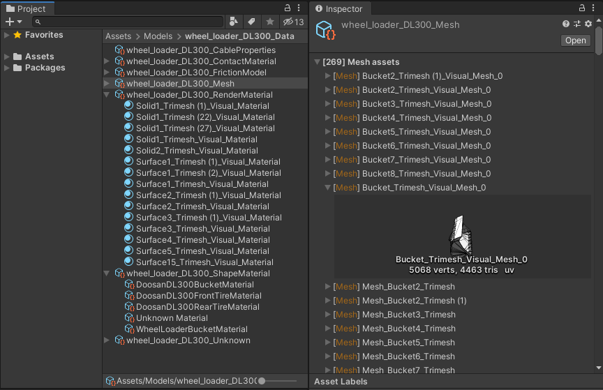
Project view and Inspector of imported assets.
To import (create a prefab) a model, right click the .agx file in the Project view and select
AGXUnity -> Import -> Selected AGX Dynamics file [prefab].
Or in an editor script (NOTE: return AGXUnityEditor.IO.AGXFileImporter.Import( filename ); is
enough, this example exemplifies how to access the assets of an imported model):
public static GameObject CreatePrefab( string filename )
{
  // .agx or .aagx files supported.
  if ( !System.IO.Path.GetExtension( filename ).ToLower().EndsWith( "agx" ) )
    return null;

  var prefab = AGXUnityEditor.IO.AGXFileImporter.Import( filename );
  if ( prefab != null ) {
    Debug.Log( "* Successfully imported " + filename + "." );
    // This component contains assets dependent data.
    var importedData = prefab.GetComponent<AGXUnity.IO.RestoredAGXFile>();
    // The directory GUID the assets were written to.
    var dir = AssetDatabase.GUIDToAssetPath( importedData.DataDirectoryId );
    // RestoredAssetsRoot is the main assets of any imported asset type.
    // These roots are always created even though there's no data.
    var roots = AGXUnityEditor.IO.Utils.FindAssetsOfType<AGXUnity.IO.RestoredAssetsRoot>( dir );
    // Printing list of UnityEngine.Material imported assets.
    var rootContainingTypeToPrint = AGXUnity.IO.RestoredAssetsRoot.ContainingType.RenderMaterial;
    // Finds System.Type given ContainingType enum.
    var typeToPrint = AGXUnity.IO.RestoredAssetsRoot.GetType( rootContainingTypeToPrint );
    // Finds and loads the materials. This is identical to
    // AGXUnityEditor.IO.Utils.FindAssetsOfType<UnityEngine.Material>( dir ).
    var renderMaterials = AGXUnityEditor.IO.Utils.FindAssetsOfType( dir, typeToPrint );

    Debug.Log( "    - Data directory: " + dir );
    Debug.Log( "    - Roots [" + roots.Length + "]:" );
    foreach ( var root in roots ) {
      var rootType = AGXUnity.IO.RestoredAssetsRoot.GetType( root.Type );
      // root.Type == Unknown is for general types, i.e., there's no
      // specific System.Type for this root type.
      if ( rootType == null )
        continue;
      Debug.Log( "          " + root.Type + " " +
                                "[" +
                                AGXUnityEditor.IO.Utils.FindAssetsOfType( dir, rootType ).Length +
                                "]" );
    }
    Debug.Log( "    - Render materials:" );
    foreach ( var renderMaterial in renderMaterials )
      Debug.Log( "          " + renderMaterial.name );
  }

  return prefab;
}
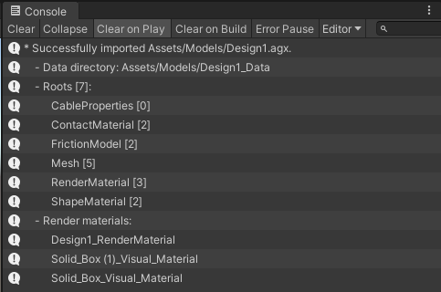
Result of the example above for a simple model with 2 contact materials, 2 friction models, 5 meshes, 3 render materials and 2 shape materials.
2.7.4. AGX Dynamics Export
AGX Dynamics supports complete and deterministic serialization. Exported AGX Dynamics files are important when something is wrong and you have to contact support. It’s possible to save the Initial state, i.e., the state in which the simulation was initialized in, or the Current state, saving the current state before the next step. See Simulation (Manager) for the Inspector interface for this.
Below is an example component which saves the simulation state at a given stride. The file is written before the simulation steps.
using System.IO;
using UnityEngine;
using AGXUnity;

public class SimulationExporter : MonoBehaviour
{
  public string BaseFilename = "Exports/simulation";
  public int Stride = 1;

  private void Start()
  {
    Directory.CreateDirectory( Path.GetDirectoryName( BaseFilename + ".agx" ) );
    Simulation.Instance.StepCallbacks.PreStepForward += OnPreStepForward;
  }

  private void OnDestroy()
  {
    if ( Simulation.HasInstance )
      Simulation.Instance.StepCallbacks.PreStepForward -= OnPreStepForward;
  }

  private void OnPreStepForward()
  {
    // We count frames from 0 so that the initial state is
    // saved independent of Stride.
    var frameCount = Time.frameCount - 1;
    var performExport = ( frameCount % Stride ) == 0;
    if ( performExport ) {
      // Filename at time 12.20s will become: simulation_t012.20.agx
      var filename = BaseFilename +
                     "_t" +
                     Time.timeSinceLevelLoad.ToString( "000.00" ) +
                     ".agx";
      var success = Simulation.Instance.SaveToNativeFile( filename );
      if ( success )
        Debug.Log( "Exporting: " + filename );
      else
        Debug.LogWarning( "Failed to export: " + filename );
    }
  }
}
2.7.5. Additional Import Components
Some components available in AGXUnity are mainly used when importing models. These components generally contain little to no actual behaviour and are mainly included to keep references to constructs in the imported file. These components include:
Assembly - Represents a collection of objects in the imported file. Functionally replaced by simple GameObjects in AGXUnity.
ObserverFrame - Represents a transform relative to an object in the imported file. Functionally replaced by the transform component in a child GameObject of the object.
2.7.6. OpenPLX Import
AGXUnity provides experimental support for importing OpenPLX models. Note that that the API and components will change as the importer updates over time.
2.7.6.1. Import Pipeline
The OpenPLX importer differs from the other importers since it is based on Unity’s ScriptedImporter which means that the Editor import step is handled automatically via Unity’s asset import step. This means that any OpenPLX-model present in the project will be imported on project startup and will be automatically up to date as changes are made to source files and their dependencies. This reduces the project size of projects with many large OpenPLX objects since only the source files are required to load the scene while the scene representation is generated dynamically.
Note
While the OpenPLX importer does take dependencies into account when deciding whether to reimport assets, it does not currently link models imported to their corresponding imported assets.
It is also possible to import models at runtime. In this case the custom ScriptedImporter
can be cirumvented by calling the OpenPLXImporter.ImportOpenPLXFile( openPlxPath ) method.
This returns generic UnityEngine.Object based on the type of the imported OpenPLX model.
If a specific type is expected then the generic version of the same method allows for specifying
the expected type of the imported object.
The import pipeline can be summarized into the following:
The OpenPLX file is parsed and an OpenPLX object tree is generated by the OpenPLX SDK.
The OpenPLX object tree nodes are recursively mapped onto corresponding AGXUnity components or assets.
Simulatable objects such as
Physics3D.SystemorPhysics3D.Bodies.RigidBodyare mapped onto Unity GameObjects and Rigid Body respectively. And for these models, the mapped objects are placed into a root GameObject which contains metadata-components for interacting with the OpenPLX tree, the OpenPLX Root and the OpenPLX Signals components.Asset objects such as
Visuals.Materials.Materialare mapped onto the corresponding asset type, whether that type is a Unity asset or an AGXUnity asset.For simulatable objects, the Signals present in the imported object are recorded in the OpenPLX Signals component for easy access.
If the import is happening at edit-time, a Unity Asset is created and populated:
If the root object is mapped to a GameObject by the mapper then it and any created assets are added to the imported Asset.
If the root object is an asset, then only that asset is added to the imported Asset.
When the simulation is run, if the imported object is simulatable, then the OpenPLX object tree is made available at run-time and components which are run-time only are mapped during initialization.
2.7.6.2. Object import
For simulatable OpenPLX models, the imported asset will be a GameObject with object hierarchy matching that of the imported OpenPLX object tree. This hierarchy contains AGXUnity components populated with the values provided in the source OpenPLX model.
To make it easier to interface with the imported model, two meta-components are placed on the imported object.
2.7.6.2.1. OpenPLX Root
The OpenPLX Root component represents the root of the OpenPLX object tree. This component contains utilities for finding the mapped component given an input OpenPLX declaration name. Additionally, the root component is responsible for performing a second mapping pass at runtime, mapping any objects that does not have a component representation in AGXUnity, with drivetrain components being a notable example.
2.7.6.2.2. OpenPLX Signals
The OpenPLX Signals component serves as a wrapper around the signaling API that OpenPLX exposes. This includes finding the signals that the model exposes, both implicitly and explicitly via OpenPLX signal interfaces.
AGXUnity provides two methods of sending and receiving signals: raw and wrapped.
The raw method consists of constructing and sending input signals, and listening for output signals directly.
To send signals with this approach, a new InputSignal is constructed with a target input endpoint, signal type,
and signal value specified explicitly after which it is passed to the OpenPLX signals component via the
SendInputSignal method. To listen to output signals, the OutputSignals list has to be iterated
to find check whether a signal was sent from the output source that one is interested in.
The wrapped method instead creates wrapper objects around OpenPLX Inputs and Outputs in the OpenPLX model.
the InputTarget wrapper has a generic SendSignal method that only requires specifying the
value to be sent. The signal type is inferred from the wrapped OpenPLX Input and the specified value and
throws an exception if they are not compatible. For outputs, the OutputSource provides similar
wrappers where the output signals are cached per OpenPLX Output. To access the cached signal values the
GetValue can be used while the generic [Try]GetValue versions additionally convert the signal
into the provided type.
2.7.6.2.3. Import options
When importing OpenPLX files there are various options used to control how the mapping is performed. These options are accessed in the inspector by selecting the imported asset in the project view.
Skip Import - Skips this OpenPLX file when importing assets. Other files using models defined in this OpenPLX file are not skipped by extension.
Hide Imported Meshes - When importing large models there might be a large amount of meshes being imported which can make it hard to navigate the subassets of the imported OpenPLX file. This option hides the imported meshes in the subasset view.
Ignore Disabled Meshes - When importing OpenPLX files that in turn import .agx archives, the visual meshes are sometimes attached to a disabled collision mesh with the same source mesh. When enabled, this option skips the import of these disabled meshes when mapping to AGXUnity objects.
Rotate Up - Since AGX use Z-up by default, many OpenPLX models might be built using Z-Up. This option applies a rotation to move the model Z-axis to the Unity Y-axis.
Imported Model - By default, the last model declared in an imported OpenPLX-file will be the one mapped to AGXUnity. This option allows this behaviour to be overridden to instead import any model declared at the root level of the file. Note that the options provided are not guaranteed to be importable or complete.
Hide Imported Visual Meshes - Similar to the Hide Imported Meshes options but instead hide the imported visual meshes.
Hide Imported Visual Materials - Hides imported visual materials.
Hide Imported Textures - Hides imported textures.
2.7.6.2.4. Visual import
OpenPLX visual definitions can contain meshes, materials, and textures in addition to the physical model. AGXUnity imports these visual assets into Unity objects and subassets so imported OpenPLX models can retain their authored appearance without requiring a separate Unity-side visual setup. For large models, the Hide Imported Visual Meshes, Hide Imported Visual Materials, and Hide Imported Textures options can be used to reduce clutter in the imported asset hierarchy while keeping the generated visuals available to the model.
2.7.6.2.5. MateConnector Mapping
In OpenPLX, MateConnectors serve an important purpose of marking points of interest in models. As such, preserving this information through the mapping process is an important aspect. In AGXUnity, this is done by mapping MateConnectors to GameObjects with ObserverFrame components. This allows for the MateConnectors present in the model to be easily visualized in the scene and referenced by other objects.
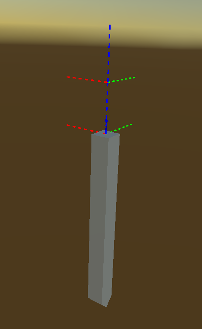
The gizmos used to visualize MateConnectors in the scene view.
Visualizing MateConnectors can, however, create a lot of clutter in the scene view in cases where the specific positions of the MateConnectors are not of interest. In this case it is possible to disable the Unity gizmos used to visualize it by toggling ObserverFrame in the Unity Gizmos menu.
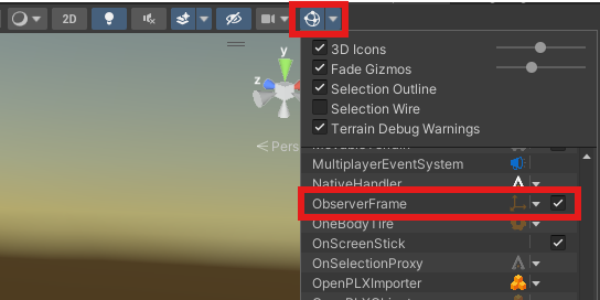
Disabling the ObserverFrame entry in the gizmos menu can help reduce visual clutter in the scene view.
2.7.6.3. Building applications with imported OpenPLX models
Special care must be taken when building and distributing applications using imported OpenPLX-files. The reason for this is that, as mentioned above, the OpenPLX-files must be available when running the built application for the runtime mapping step to work. This means that any relative imports of OpenPLX-files must be mirrored in the built application. To make this easier, AGXUnity provides a post-build hook which copies OpenPLX-files in the project to the build directory. Specifically, asset at path Assets/<subdirs>/file.openplx will be copied to <build data dir>/OpenPLX/<subdirs>/file.openplx and during runtime, a corresponding substitution will be made when importing OpenPLX-files using the API. Note that this means that relative references crossing the project boundary might break after build.
The copier will do its best to find non-OpenPLX dependencies of files as well and will attempt to find references to files in strings as well as import expressions. This process, however, relies on the OpenPLX-file being importable in in the first place. As this is not always the case, this process might fail, in which case a warning will be issued on build and the dependencies of the file should be copied manually instead to ensure they are available at runtime.
2.7.6.4. Configuring Bundle Directories
One of the core ideas of OpenPLX is to allow the definition of custom bundles. When later using bundles,
the OpenPLX-runtime requires that the path to the bundles be provided to the runtime context as the dependant
model is parsed. In AGXUnity, this is done by specifying the path to the bundle in the AGXUnity settings
accessed from the top menu AGXUnity > Settings. The path mapping described in Building applications with imported OpenPLX models
is additionally applied to any bundle paths specified.
2.7.6.5. Limitations
Since OpenPLX is still a new format under heavy development there are a few limitations to the importer.
AGXUnity currently only supports importing a single model from an OpenPLX file. This means that “Dummy files” have to be created which define a new model for each model in a source file that should be imported.
Since a lot of new bundles and models are being added to OpenPLX continuously, there might be some models which are not implemented by the AGXUnity mapper. Additionally, not every model is supported by AGXUnity, In these cases the importer might warn and ignore instead of failing the import altogether.
There is currently no link between imported models, instead each imported model is considered “complete” in the sense that they do not rely on the import of other files but might also cause the project library directory to become large if there are many variants of a large model in the project. Consider toggling the Skip import option for unused models if this becomes a problem.
2.8. Editor Settings
The AGX Dynamics for Unity plugin provides a few editor settings which affect the behaviour of the plugin.
These settings include keybindings for plugin functionality and build options. These settings can be accessed
by selecting AGXUnity/Settings in the top menu or by going to the project settings and selecting the
AGX Settings tab.
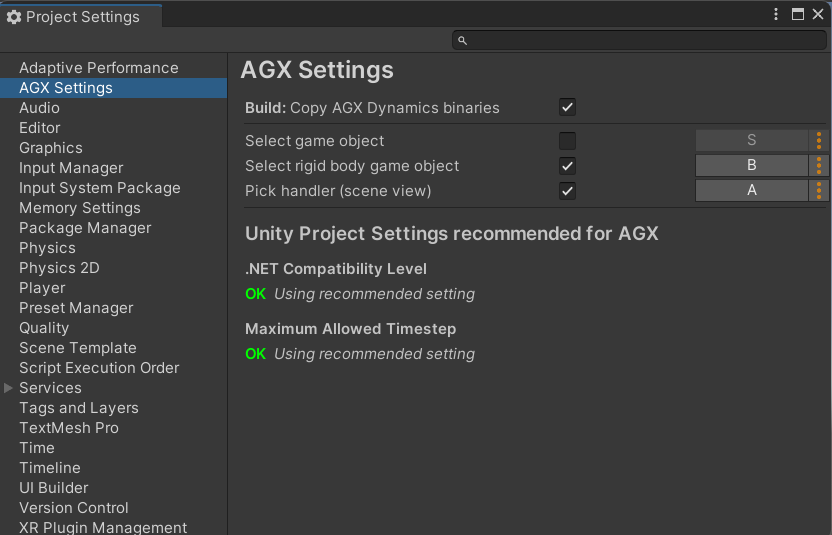
The AGX Dynamics for Unity Editor Settings window.
Overview of the available settings:
Copy AGX Dynamics binaries: By default, the unity build process does not copy any dependent DLLs to the build directory. This means that native plugins such as AGXUnity, might have trouble finding the DLLs when the application is run. Checking this option adds an additional step to the build process which copies the AGX DLLs to the application build directory.
Keybindings:
Select game object: When clicking on a visual object in the scene view, the Shape component (if any) associated with that visual object is selected. When the key bound to this option is held however, a menu is shown with the scene hierarchy up to the world node, from which the desired GameObject can be selected.
Select rigid body game object: When this key is pressed, the closest, parent Rigid Body component is selected.
Pick handler (scene view): It is often useful to have a way of manipulating objects in the scene directly when running the simulation. When the key bound to this option is held, clicking and dragging on an object in the scene view creates a Constraint between the clicked object and the mouse cursor. Left clicking creates a Ball joint, limiting the translation. Middle clicking creates a lock joint, limiting all DoFs. Right clicking creates an angular lock joint, limiting rotation.
Unity Project Settings recommended for AGX: When using AGXUnity, some of the Unity project options might cause AGXUnity to behave poorly. For this reason, the AGXUnity settings provide a “quick fix” list of unity settings which can be set to reasonable values by AGXUnity. Ignoring these might cause build or performance issues.
.NET Runtime - The plugin only supports the Mono scripting backend currently and selecting another value might result in crashes or other issues when launching a build application.
Maximum Allowed Timestep - Unity can run extra timesteps to “catch up” to real time when falling behind. This is generally not recommended as AGXUnity applications are typically bounded by the Fixed Update time rather than the rendering. Which can cause further slowdowns and long frame times. Therefore it is recommended to set this setting to the same as the Fixed Timestep. Also see Stepping Mode.
Disable Unity Physics Auto Simulation - Typically when using AGXUnity, there is no need for the built in physics to also step as the simulation is handled by AGX. For this reason, it is recommended that the default physics stepping be disabled as to avoid confusion caused by adding the wrong components to objects and similar issues.