10. Constraints
Constraints represent geometrical relationships between bodies. For example, a door hanging in its frame with hinges can be modeled in a simulation with one or several Constraints. A tire attached to a wheel hub is another example where a Constraint can be used.
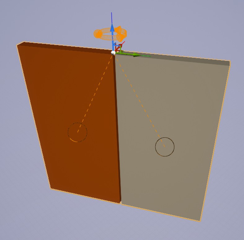
The image below show two boxes constrained using a Hinge Constraint.
10.1. Creating Constraints
Constraints can be created in the same way as Rigid Bodies and Shapes are created, by adding Components to Actors. Another way to create Constraints is through the Constraint creation wizard found in the AGX Dynamics Mode.
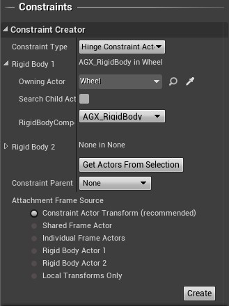
The constraint creation wizard.
Select the type of Constraint to create, the bodies that should be constrained, and the way attachment frames should be computed. For the example, create a Hinge Constraint having a wheel as it’s first body and leave the second body blank. This will constrain the wheel to the world.
Orange circles are rendered to indicate the constrained bodies when an actor containing one or more Constraints is selected. When a Constraint component is selected in the Details panel then the full Constraint gizmo is rendered. The Constraint gizmo is a visualization of both the Constraint frame and the free degree(s) of freedom, if any. A Prismatic has one free translational axis, the z-axis, which can be seen in the image below.
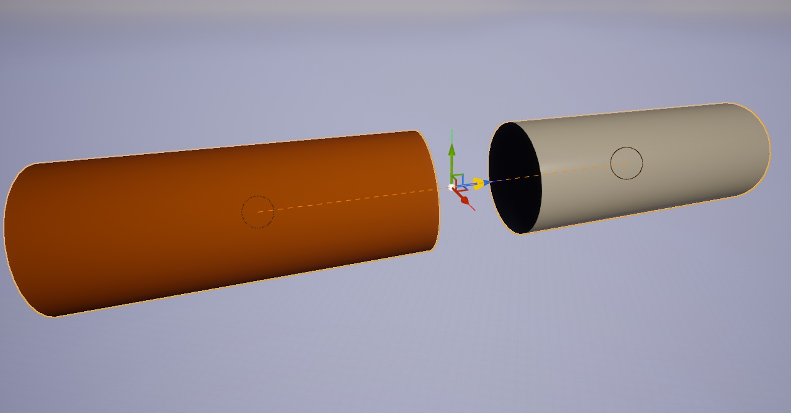
Prismatic Constraint gizmo. The yellow arrow indicate the axis of translation.
10.1.1. Secondary Constraints
To enable motors, friction controllers and more, one can enable one or several of the Secondary Constraints of a Constraint Component. This is done from the AGX Secondary Constraint category of the Details panel when the Constraint component is selected.
Below is an example where the Target Speed Controller is enabled and set to a speed of 100 degrees per second.
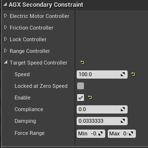
Settings for the Target Speed Controller
10.2. Hinge Constraint

Hinge Constraint gizmo. The yellow arrows indicate the free degrees of freedom.
A Hinge Constraint allows for rotations around the z axis. All other degrees of freedoms are locked. It has the following Secondary Constraints:
Electric Motor Controller
Friction Controller
Lock Controller
Range Controller
Target Speed Controller
10.3. Prismatic Constraint
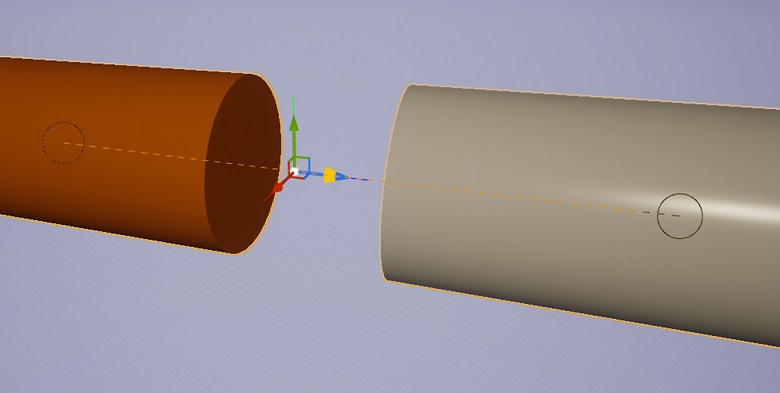
Prismatic Constraint gizmo. The yellow arrows indicate the free degrees of freedom.
A Prismatic Constraint allows for translations along the z axis. All other degrees of freedoms are locked. It has the following Secondary Constraints:
Electric Motor Controller
Friction Controller
Lock Controller
Range Controller
Target Speed Controller
10.4. Lock Constraint
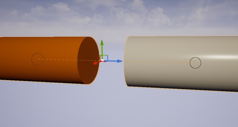
Lock Constraint gizmo.
For a Lock Constraint, all degrees of freedoms are locked. It has no Secondary Constraints.
10.5. Ball Constraint

Ball Constraint gizmo. The yellow arrows indicate the free degrees of freedom.
A Ball Constraint allows for rotations around the x, y and z axis. All other degrees of freedoms are locked. It has no Secondary Constraints.
10.6. Cylindrical Constraint
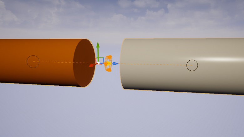
Cylindrical Constraint gizmo. The yellow arrows indicate the free degrees of freedom.
A Cylindrical Constraint allows for rotations and translations around the z axis. All other degrees of freedoms are locked. It has the following Secondary Constraints:
Electric Motor Controller (one for rotation + one for translation)
Friction Controller (one for rotation + one for translation)
Lock Controller (one for rotation + one for translation)
Range Controller (one for rotation + one for translation)
Target Speed Controller (one for rotation + one for translation)
Screw Controller
10.7. Distance Constraint
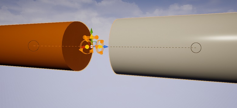
Distance Constraint gizmo.
A Distance Constraint ensures a constant distance is kept. The bodies may translate and rotate freely as long as the distance is constant. It has no Secondary Constraints.
10.8. Graphical Representation Settings
All Constraints have graphical representations, i.e. are rendered to the screen when an actor containing one or several Constraints is selected.
These renderings are scaled in such a way that they keep a constant size as measured on the screen. This behavior is similar to the regular transformation gizmo.
To keep these renderings from cluttering the screen when moving far away from a selected Actor, a maximum distance within which this scaling is active, is available as a plugin setting.
To change this setting, select Edit > Project Settings... > Plugins > AGX Dynamics and in the category Rendering change the value of Constraint Visualization Scaling Distance Max.